Annular interbody fusion system under spine total endoscope

An intervertebral fusion cage and annular technology, which is used in spinal implants, medical science, prostheses, etc., can solve the problem that the contact area of ​​the upper and lower vertebral bodies cannot be controlled, the position of the cage does not match the preset position, and the fusion of the upper and lower vertebral bodies is affected. effect and other issues, to achieve good fusion effect, improve fusion effect, and shorten operation time.

Pending Publication Date: 2021-12-21
NINGBO HICREN BIOTECH
View PDF8 Cites 0 Cited by
  • Summary
  • Abstract
  • Description
  • Claims
  • Application Information

AI Technical Summary

Problems solved by technology

The defect of this design is: when using, the first filler with self-solidification is filled between the container and the mesh body, and the expanded shape of the mesh body is uncontrollable, resulting in an uncontrollable contact area with the upper and lower vertebral bodies , making the bone graft area too small to affect the fusion effect of the upper and lower vertebral bodies
The defect of this design fusion cage is that: after entering the intervertebral space, the core pin is withdrawn. During the bone grafting process, the head end of the mesh bag will inevitably retract with the expansion of the mesh bag, resulting in the position of the fusion cage after implantation being different from the preset position. The position does not match; after the bone graft is completed, the fusion device needs to be sealed with a mouth tie device, which increases the operation steps of the operation
The defect of this design fusion cage is that although the height of the mechanism can be raised, it is not scalable in the width direction. If it wants to pass through the slender working channel of the endoscope, the width must be narrow, and the length is limited by the size of the vertebral body. Eventually, the area in contact with the upper and lower endplates is relatively small, resulting in excessive local pressure of the vertebral body, which will cause the fusion cage to sink into the interior of the vertebral body for a long time

Method used


Image

  • Annular interbody fusion system under spine total endoscope
  • Annular interbody fusion system under spine total endoscope
  • Annular interbody fusion system under spine total endoscope

Examples


Embodiment 1

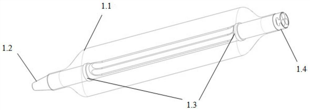
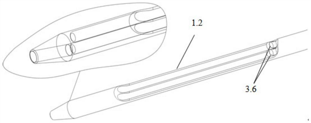
[0065] Please refer to Figure 2a-2b As shown, the present embodiment provides a spinal full-endoscopic annular intervertebral fusion system, including a foldable annular intervertebral fusion device 1, the annular intervertebral fusion device 1 includes a balloon 1.1, a multi-lumen tube 1.2, a developing ring 1.3 and connecting ring 1.4; the inner surfaces of the two ends of the balloon 1.1 are adhered to the outer surfaces of the two ends of the multi-lumen tube 1.2; the multi-lumen tube 1.2 is provided with three channels, and the bone cement channel communicates with the distal outlet of the multi-lumen tube 1.2, The distal ends of the two bone cement channels are closed, and the side walls of the two bone cement channels are located in the balloon 1.1. The structure of 3.6 is that the distal end is sealed, and there is a gap on the side of the distal end; the two developing rings 1.3 are hot-melted and fixed to the two ends of the multi-lumen tube 1.2 in the balloon 1.1, ...

Embodiment 2

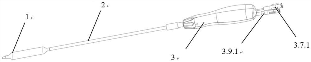
[0068] Please refer to figure 1 As shown, this embodiment provides a total endoscopic annular intervertebral fusion system for the spine, including the annular intervertebral fusion device 1 in Embodiment 1, the fusion device grasping and fixing part 2, the handle part 3 and the guide wire 4; in,

[0069] like Figure 3a-3b Among them, the grasping and fixing part 2 of the fusion device includes a connecting inner tube 2.1 and an outer tube 2.2 sleeved on the outer surface of the connecting inner tube 2.1. The proximal end of the connecting inner tube 2.1 is provided with an inner tube fitting 2.4, and the proximal end of the outer tube 2.2 is provided with The outer pipe driving part 2.3, the outer surface of the inner pipe matching part 2.4 is threadedly matched with the inner surface of the outer pipe driving part 2.3; the far end connecting the inner pipe 2.1 is matched with the structure of the connecting ring 1.4;

[0070] like Figure 4a-4b In the handle part 3, thro...

Embodiment 3

[0076]This embodiment provides the operation mode of the spinal all-endoscopic annular intervertebral fusion system in Embodiment 2, which specifically includes the following steps:

[0077] S1 Guide wire 4 implantation: During the operation, after the intervertebral disc is processed, first put the distal end of the guide wire 4 into the opening of the working channel, and then slowly push it along the working channel until the pre-shaped area of ​​the guide wire 4 passes completely. After the working channel, restore the pre-shaped coiled shape. At this time, the coiled area is just located in the intervertebral disc. Make sure that the guide wire 4 is placed in place through CT filming;

[0078] S2 Annular Intervertebral Fusion 1 Implantation and Looping: Insert the proximal end of the guide wire 4 into the bone cement channel in the multi-lumen tube 1.2, and the proximal end of the guide wire 4 protrudes from the bone cement Luer joint 3.7.1, After the guide wire 4 is stre...


PUM


Abstract

The invention discloses an annular interbody fusion system under a spine total endoscope. The fusion system comprises a foldable annular interbody fusion cage, and the annular interbody fusion cage comprises a balloon, a multi-cavity tube, a developing ring and a connecting ring. After the annular interbody fusion cage is coiled into a preset shape under action of a guide wire, bone cement is injected into the annular interbody fusion cage, and the bone cement stably supports the intervertebral space after being solidified. According to the annular interbody fusion system, whole-course visual surgical operation in a spine endoscope channel is achieved, the operation is safer, minimally invasive spine endoscopic operation is achieved, the operation is more minimally invasive, nerve traction and harassment are reduced, a risk of postoperative nerve complications is reduced, bleeding in the operation is reduced, a prognosis effect of a patient is improved, and operation time is shortened.

Description

technical field [0001] The invention relates to the field of medical instruments, in particular to a circular intervertebral fusion system under total endoscope for the spine. Background technique [0002] Degenerative diseases of the spine and its structural damage are an important cause of neck, shoulder, waist, and leg pain, sensory and motor function impairment or even loss. In the 1950s, Cloward first proposed Posterior Lumbar Fusion (PLIF), which has developed into one of the basic procedures of spinal surgery today. In 1986, Badgy and Kuslich designed an intervertebral fusion device (Cage) suitable for the human body, namely the BAK system. Since then, intervertebral bone graft fusion technology has been greatly developed and has become a basic surgical method for the treatment of spinal degenerative diseases and structural injuries. [0003] The principle of the intervertebral fusion is that the diseased intervertebral space is the center. After the intervertebral ...

Claims


Application Information

Patent Timeline
Patent Type & Authority Applications(China)
IPC IPC(8): A61F2/44A61F2/46
CPCA61F2/4455A61F2/4601A61F2/4611
Inventor 姚益奇姚柏艇卓清山张鹏云
Owner NINGBO HICREN BIOTECH
Why Eureka
Try Eureka