
An industrial robot deceleration device

An industrial robot and deceleration device technology, which is applied in the field of robots, can solve problems such as the influence of the working environment of the device, damage to internal components, and reduced assembly accuracy, so as to avoid errors, reduce noise, and reduce wear and tear.

Active Publication Date: 2022-02-08
思岚机器人(南通)有限公司
View PDF8 Cites 0 Cited by
  • Summary
  • Abstract
  • Description
  • Claims
  • Application Information

AI Technical Summary

Problems solved by technology

[0006] Aiming at the deficiencies of the prior art, the present invention provides an industrial robot deceleration device, which solves the problem that the assembly accuracy tends to decrease after working for a long time, so that the error after replacement increases, the noise during operation is large, and it is easy to damage the device. Influenced by the working environment, the increase in heat during internal work is likely to cause damage to internal components

Method used


Image

  • An industrial robot deceleration device
  • An industrial robot deceleration device
  • An industrial robot deceleration device

Examples


Embodiment 1

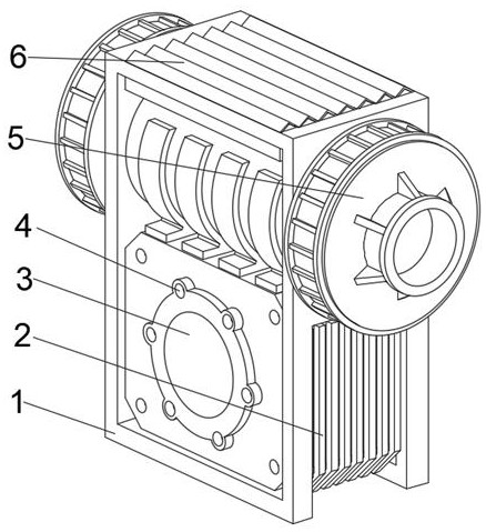
[0041] see Figure 1-6 , the present invention provides a technical solution: an industrial robot deceleration device, including a main body 1, a cover plate 3 is fixedly connected to the middle of the front bottom of the main body 1, and a communication hole 4 is opened on both sides of the front of the cover plate 3, and the main body 1 The bottom of both sides of the outer wall is fixedly connected with the support plate 2, and the middle position of the top of the inner wall on both sides of the main body 1 is provided with a deceleration device 5. Dustproof plate 6;

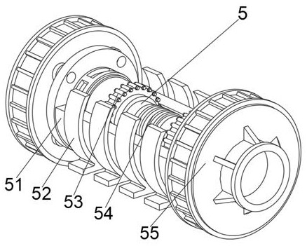
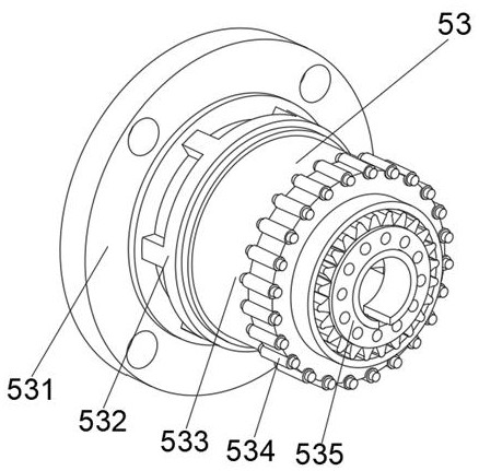
[0042] The speed reduction device 5 includes a synchronous sleeve 54, the two ends of the synchronous sleeve 54 are fixedly connected with a linkage mechanism 53, and the bottom of the linkage mechanism 53 is provided with a connecting housing 51, and both sides of the linkage mechanism 53 penetrate the connecting housing 51 and extend to the connecting housing 51. Outside the housing 51, the bottom of the ...

Embodiment 2

[0048] see Figure 1-6 , on the basis of Embodiment 1, the present invention provides a technical solution: a method for using an industrial robot deceleration device, step 1: install the equipment, and fix the dustproof plate 6 with the main body 1, and install the deceleration device 5 is fixedly connected with the main body 1, and connects the main body 1 with the driver;

[0049] Step 2: The internal rotation of the transmission chamber generated by connecting the housing 51 and the synchronous sleeve 54 is carried out, and as the linkage mechanism 53 and the synchronization sleeve 54 rotate together, the fastening mechanism 55 and the linkage mechanism 53 are fixedly connected to make it It plays the role of driving the internal emergency stop fastening, and fixedly connects the connection housing 51 with the balance side plate 52;

[0050] Step 3: use the reduction gear 535 to precisely control the rotating parts, connect the fixed connection plate 531 with the rigid re...


PUM


Abstract

The invention discloses an industrial robot deceleration device, which comprises a main body, a cover plate is fixedly connected to the middle position of the front bottom of the main body, communicating holes are opened on both sides of the front of the cover plate, and the bottoms of the outer walls of the two sides of the main body A support plate is fixedly connected, and a deceleration device is provided at the middle of the top of the inner wall on both sides of the main body. The two sides of the deceleration device pass through the main body and extend to the outside of the main body. Involved in the field of robotics. The industrial robot deceleration device, when decelerating and stopping the device, the uneven surface of the dust plate can collect a certain amount of dust, which effectively improves the transmission stiffness of the deceleration force in a limited space, making it further increase. The ultimate bearing capacity of the device is increased, and the precision of the internal deceleration control of the device is increased, which is convenient for reducing the noise when the device rotates and decelerates, and is conducive to avoiding errors caused by the overall installation in the later stage.

Description

technical field [0001] The invention relates to the technical field of robots, in particular to an industrial robot deceleration device. Background technique [0002] The deceleration device is one of the core components of the robot. Its function is to transmit the power of the servo motor, reduce the speed of the servo motor and amplify the torque, so as to accurately control the movement of the robot and carry related loads. The reduction gears for robots are divided into three categories: planetary reducers, harmonic reducers and RV reducers. Among them, planetary reducers are mostly suitable for small reduction ratio conditions (reduction ratio i≤50), harmonic reducers and RV reducers are mostly used for large reduction ratio conditions (reduction ratio i≥50), and the industrial robot industry is developing rapidly , The demand for high-performance precision reducers is increasing day by day. [0003] According to a robot deceleration device disclosed in Chinese Paten...

Claims


Application Information

Patent Timeline
Patent Type & Authority Patents(China)
IPC IPC(8): B25J9/10B25J19/00
CPCB25J9/10B25J19/0054B25J19/0075
Inventor 夏吴斌
Owner 思岚机器人(南通)有限公司
Learn More