Current transformer production line and using method thereof
A current transformer and production line technology, which is applied in the direction of conveyor objects, conveyor control devices, transportation and packaging, etc., can solve problems such as unfavorable use, troublesome placement and transportation of current transformers, and failure of assembly line production
- Summary
- Abstract
- Description
- Claims
- Application Information
AI Technical Summary
Problems solved by technology
Method used
Image
Examples
Embodiment 1
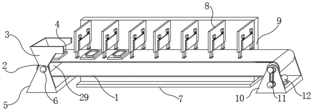
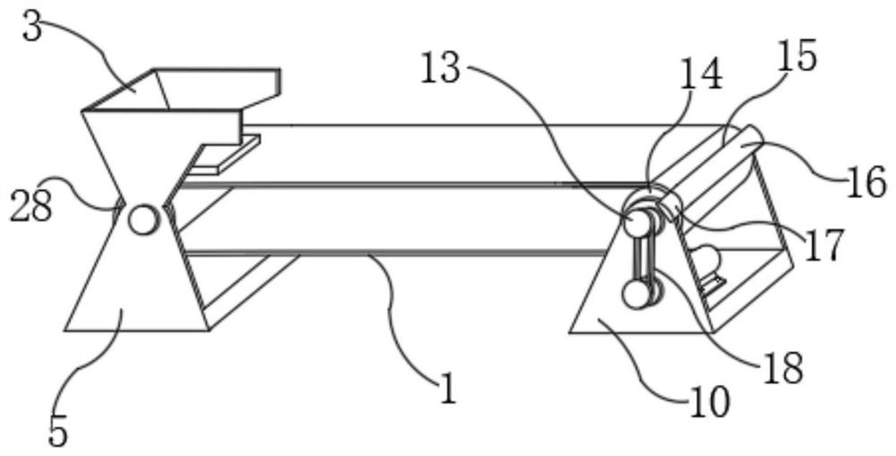
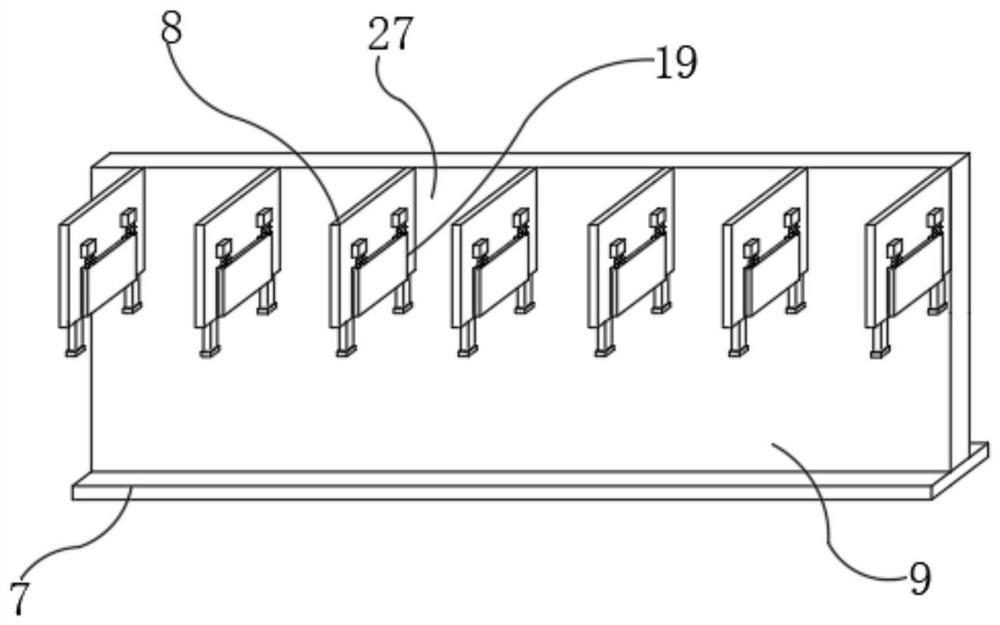
[0035] Such as Figure 1-7 As shown, a current transformer production line, including the assembly line conveyor belt 1, processing seat 9, feed positioning support frame 5, discharge positioning support frame 10, the upper end of the feed positioning support frame 5 is movably installed with a transmission roller 2 , the upper end of the discharge positioning support frame 10 is movable to install the No. 2 transfer roller 14, the assembly line conveyor belt 1 is located at the outer position of the No. 1 transfer roller 2 and the No. 2 transfer roller 14 to move, and the lower end of the processing seat 9 is positioned and connected to a positioning base 7. The front end of the processing seat 9 is positioned with a processing partition 8 .
[0036] The outside of the processing partition 8 is equipped with a drive cylinder 20 and a movable baffle 19, a slide rail 24 is installed between the movable baffle 19 and the processing partition 8, a lifter 21 is installed between t...
Embodiment 2
[0042] On the basis of Example 1, as Figure 1-7 As shown, a current transformer production line, including the assembly line conveyor belt 1, processing seat 9, feed positioning support frame 5, discharge positioning support frame 10, the upper end of the feed positioning support frame 5 is movably installed with a transmission roller 2 , the upper end of the discharge positioning support frame 10 is movable to install the No. 2 transfer roller 14, the assembly line conveyor belt 1 is located at the outer position of the No. 1 transfer roller 2 and the No. 2 transfer roller 14 to move, and the lower end of the processing seat 9 is positioned and connected to a positioning base 7. The front end of the processing seat 9 is positioned with a processing partition 8 .
[0043] The outside of the processing partition 8 is equipped with a drive cylinder 20 and a movable baffle 19, a slide rail 24 is installed between the movable baffle 19 and the processing partition 8, a lifter 21 ...
Embodiment 3
[0047] On the basis of Example 2, such as Figure 1-7 As shown, a current transformer production line, including the assembly line conveyor belt 1, processing seat 9, feed positioning support frame 5, discharge positioning support frame 10, the upper end of the feed positioning support frame 5 is movably installed with a transmission roller 2 , the upper end of the discharge positioning support frame 10 is movable to install the No. 2 transfer roller 14, the assembly line conveyor belt 1 is located at the outer position of the No. 1 transfer roller 2 and the No. 2 transfer roller 14 to move, and the lower end of the processing seat 9 is positioned and connected to a positioning base 7. The front end of the processing seat 9 is positioned with a processing partition 8 .
[0048] A method for using a current transformer production line, comprising the following steps:
[0049] S1: Assemble the assembly line, install the feed positioning support frame 5 and the discharge positio...
PUM
 Abstract
Description
Claims
Application Information
 - R&D
- Intellectual Property
- Life Sciences
- Materials
- Tech Scout
- Unparalleled Data Quality
- Higher Quality Content
- 60% Fewer Hallucinations
Browse by: Latest US Patents, China's latest patents, Technical Efficacy Thesaurus, Application Domain, Technology Topic, Popular Technical Reports.
© 2025 PatSnap. All rights reserved.Legal|Privacy policy|Modern Slavery Act Transparency Statement|Sitemap|About US| Contact US: help@patsnap.com


