Assembly type laminated slab and composite beam connecting structure and construction method

A technology for connecting structures and construction methods, which is applied to truss structures, elongated structural members for load-bearing, structural elements, etc., can solve the problems of cost increase, waste of steel bars, low construction efficiency, etc., and achieve reliable connection force , improve the shear performance and improve the overall effect

Pending Publication Date: 2021-11-26
筑友智造建设科技集团有限公司
View PDF12 Cites 1 Cited by
  • Summary
  • Abstract
  • Description
  • Claims
  • Application Information

AI Technical Summary

Problems solved by technology

However, the laminated floor slab also has obvious disadvantages. The rigidity of the prefabricated floor slab is small, and it is easy to crack during hoisting and transportation, which greatly limits its application.
In view of this, the reinforced truss laminated slab proposed by the Chinese patent CN201320114445.3 overcomes the above-mentioned shortcomings of the laminated floor slab, but has the following disadvantages: the amount of truss reinforcement is large, which only improves the rigidity of the prefabricated slab. The impact on performance is small, the waste of steel bars is serious, and the cost is also greatly increased
Chinese patent CN201620040756.3 proposes a laminated slab with concrete ribs. Although it can effectively improve the stiffness of the prefabricated floor, the connection between the floor and the ribs is relatively complicated, and the production of the laminated slab requires secondary pouring. brings difficulties
During the construction of traditional composite beams, the concrete slabs are often cast-in-place construction methods, but this method requires complex formwork installation and removal on site, and the construction efficiency is low, and the environmental pollution is relatively large
Chinese patent CN201920120142.X proposes a laminated slab composite beam, but it has the following disadvantages: the rigidity of the prefabricated slab is small, and the prefabricated slab is easy to crack during transportation and hoisting
Patent CN201910072931.5 is also a laminated slab composite beam. The prefabricated slab is provided with truss reinforcement. The truss reinforcement can be simplified as a rib on the prefabricated slab, which can effectively improve the rigidity of the prefabricated slab and greatly reduce the prefabricated slab. The risk of cracking during transportation and hoisting; but there are problems: the amount of truss reinforcement is very large, which has little impact on the mechanical performance of the composite beam after the laminated layer is poured, the waste of reinforcement is serious, and the cost is also greatly increased

Method used


Image

  • Assembly type laminated slab and composite beam connecting structure and construction method
  • Assembly type laminated slab and composite beam connecting structure and construction method
  • Assembly type laminated slab and composite beam connecting structure and construction method

Examples


Embodiment 1

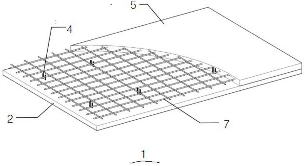
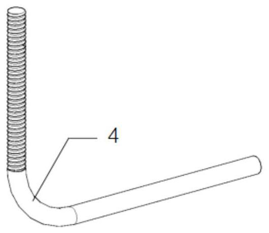
[0039] See attached figure 1 to attach Figure 5 In this example, the connection structure between the prefabricated laminated slab 1 and the composite beam 10 includes the laminated slab 1 and the composite beam 10. The laminated slab 1 includes a prefabricated layer and a post-cast layer 3, and the prefabricated layer includes a prefabricated floor 2 and multiple A shearing reinforcement 4, the bottom ends of multiple shearing reinforcements 4 are all anchored in the prefabricated floor 2, and the tops are all exposed to the prefabricated floor 2, the post-casting layer 3 includes post-casting concrete 5 and surface reinforcement 6, the surface reinforcement 6 Set on the upper surface of the prefabricated layer, the post-cast concrete 5 is poured on the upper surface of the precast floor 2, the tops of the multiple shear reinforcement bars 4 and the surface layer steel bars 6 are all anchored in the post-cast concrete 5; the composite beam 10 includes a steel beam 8 And a p...

Embodiment 2

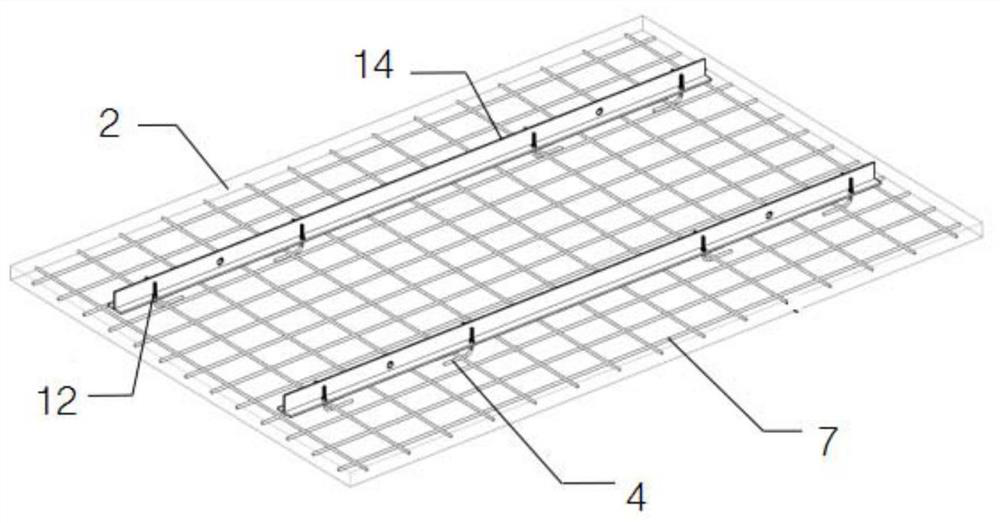
[0054] See attached Figure 6 To illustrate, in the connection structure between the prefabricated laminated slab 1 and the composite beam 10 of this embodiment, two prefabricated layers are relatively placed on both sides of the steel beam 8 to form a cross-beam patchwork, and a There are a plurality of additional ribs 11, the additional ribs 11 straddle the joints of the span beams and the two ends are respectively placed on the surfaces of the two precast layers, the surface layer steel bars 6 placed on the surfaces of the two precast layers are connected to form a whole, and the surfaces of the two precast layers are poured The post-cast concrete 5 is connected to form a whole. The first prefabricated layer 17 and the second prefabricated layer 18 are placed on opposite sides of the surface of the steel beam 8 respectively, and a plurality of additional ribs 11 parallel to each other are placed at the seams between the first prefabricated layer 17 and the second prefabrica...


PUM


Abstract

The invention provides an assembly type laminated slab and composite beam connecting structure and a construction method. The assembly type laminated slab and composite beam connecting structure comprises a laminated slab and a composite beam, wherein the laminated slab comprises a prefabricated layer and a post-pouring layer, the prefabricated layer comprises a prefabricated bottom plate and a plurality of shear reinforcements, the bottom ends of the shear reinforcements are anchored on the prefabricated bottom plate, the top ends of the shear reinforcements are exposed, the composite beam comprises a steel beam and a plurality of high-strength bolt sets detachably connected to the surface of the steel beam, the bottom face of one side of the prefabricated layer is placed on the surface of the steel beam, a splicing seam between the steel beam and the prefabricated layer is filled with post-pouring concrete on the prefabricated bottom plate, and the high-strength bolt sets are anchored in the post-pouring concrete at the splicing seam. The construction method of the assembly type laminated slab and composite beam connecting structure comprises the steps that S1, the prefabricated layer is produced; S2, the composite beam is installed, hoisted and positioned, and the prefabricated layer is hoisted and placed on the steel beam; and S3, surface layer steel bars are laid, and post-pouring concrete is poured to fill an abutted seam between the steel beam and the prefabricated layer. The connecting structure of the laminated slab and the composite beam is reliable in stress, the steel beam can be replaced, and construction is convenient.

Description

technical field [0001] The invention belongs to the technical field of prefabricated buildings, and in particular relates to a connection structure between prefabricated laminated slabs and composite beams and a construction method thereof. Background technique [0002] Compared with cast-in-place slabs, laminated slabs have the advantages of less on-site formwork, high production efficiency, low environmental pollution, and fast construction speed. However, the laminated floor slab also has obvious disadvantages. The rigidity of the prefabricated floor slab is small, and it is easy to crack during hoisting and transportation, which greatly limits its application. In view of this, the reinforced truss laminated slab proposed by the Chinese patent CN201320114445.3 overcomes the above-mentioned shortcomings of the laminated floor slab, but has the following disadvantages: the amount of truss reinforcement is large, which only improves the rigidity of the prefabricated slab. T...

Claims


Application Information

Patent Timeline
Patent Type & Authority Applications(China)
IPC IPC(8): E04B1/38E04B5/17E04C3/04E04G21/00
CPCE04B1/38E04B5/17E04C3/04E04G21/00E04C2003/0452E04C2003/0465
Inventor 陈超陈甫亮施明哲
Owner 筑友智造建设科技集团有限公司
Why Eureka
Try Eureka