Rotary detonation combustion chamber adopting pneumatic inner column

A combustion chamber and detonation technology, applied in combustion chambers, continuous combustion chambers, combustion methods, etc., can solve the problems of unfavorable thermal cycle efficiency, increase the contact area between fresh air and high-temperature gas, and increase the proportion of fresh air. The effect of improving circumferential uniformity, reducing loss and full combustion

Active Publication Date: 2021-12-03
NORTHWESTERN POLYTECHNICAL UNIV
View PDF5 Cites 2 Cited by
  • Summary
  • Abstract
  • Description
  • Claims
  • Application Information

AI Technical Summary

Problems solved by technology

The same as the annular combustor, the oxidant and fuel are still supplied into the combustor through the injector unit arranged on the outside. After the rotating detonation combustion products are generated outside the combustor, part of the combustion products will enter the central area of ​​the combustor due to no inner column restriction , staying in the original inner column position for a short time, which greatly increases the contact area between fresh mixed gas and high-temperature gas, resulting in an increase in the proportion of fresh mixed gas participating in slow combustion combustion, which is not conducive to the improvement of thermal cycle efficiency

Method used


Image

  • Rotary detonation combustion chamber adopting pneumatic inner column
  • Rotary detonation combustion chamber adopting pneumatic inner column
  • Rotary detonation combustion chamber adopting pneumatic inner column

Examples


specific Embodiment

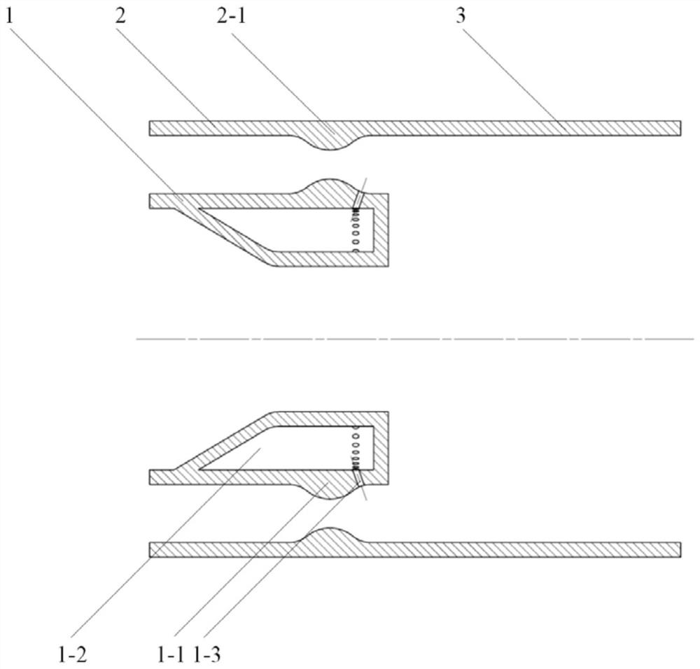
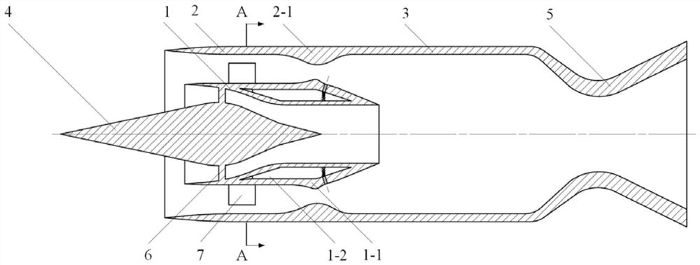
[0022] refer to figure 2 , when the rotary detonation combustor using the aerodynamic inner column in the present invention is applied to a ramjet engine, the injector housing 2 is optimized as the wall surface of the air inlet in this embodiment, and the flow divider 1 divides the air inlet into outer culverts and connotation, the inlet culvert is composed of the injector shell 2, the outer wall of the diverter and 6 outer culvert support plates 7 connecting the two, and the connotation of the inlet is composed of the inner wall of the diverter and the diversion cone 4 and the connection between the two It is composed of 6 inner support plates 6 . Inner diameter of combustion outer ring 3 D 1 , followed by the Laval nozzle 5.

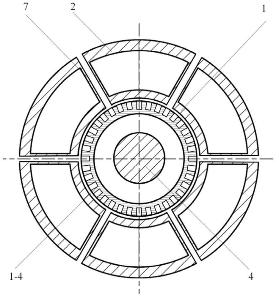
[0023] refer to image 3 , the interior of the outer culvert support plate 7 is a fuel supply passage, which uniformly supplies liquid fuel into the fuel storage tank 1-2 in the circumferential direction, and the fuel storage tank is designed as a ...


PUM


Abstract

The invention provides a rotary detonation combustion chamber adopting a pneumatic inner column. The rotary detonation combustion chamber comprises an injection head part and a combustion chamber body part. The injection head part comprises a flow divider and an injector shell, an annular oxidant airflow channel is defined by the outer wall of the flow divider and the injector shell, fuel injection holes are located in the downstream of a throat of an oxidant airflow channel, and fuel and an oxidant are mixed and then conduct rotary detonation combustion on the outer side of the combustion chamber body; and inert gas or the oxidant enters the combustion chamber body along the airflow channel defined by the inner wall of the flow divider, the pneumatic inner column flowing in the axial direction is generated, the central area of the combustion chamber body is occupied, rotating detonation products are prevented from flowing towards the center, and losses generated when rotating detonation waves expand towards the inner side are reduced. According to the rotary detonation combustion chamber adopting the pneumatic inner column provided by the invention, part of the rotating detonation products are prevented from being temporarily retained in the center area, the proportion of fresh mixed gas participating in slow combustion is reduced, the thermal cycle efficiency of the combustion chamber is improved, and meanwhile the pneumatic inner column does not need to be cooled. The rotary detonation combustion chamber can be applied to the technical field of rotary detonation propulsion.

Description

technical field [0001] The invention relates to the technical field of rotary detonation propulsion, in particular to a rotary detonation combustion chamber using a pneumatic inner column. Background technique [0002] The rotary detonation engine is a new type of engine based on rotary detonation combustion. Compared with the traditional jet engine based on slow combustion combustion, the thermal cycle efficiency is higher and the structure is simpler. Therefore, rotating detonation engines have attracted much attention in the propulsion field in recent years. [0003] The rotating detonation combustor usually adopts an annular structure with an inner column, and an annular channel is formed by the outer ring of the combustion chamber and the inner column. The oxidant and fuel are supplied axially from the head of the combustion chamber, and the rotating detonation wave rotates and propagates along the circumference of the combustion chamber, continuously consuming the com...

Claims


Application Information

Patent Timeline
Patent Type & Authority Applications(China)
IPC IPC(8): F23R3/52F23R3/28
CPCF23R3/52F23R3/28
Inventor 范玮焦中天王可赵明皓
Owner NORTHWESTERN POLYTECHNICAL UNIV
Why Eureka
Try Eureka