
Transfer mechanism

A switch and substrate technology, applied in electrical components, semiconductor/solid-state device manufacturing, circuits, etc., can solve problems such as low yield of transfer mechanism, and achieve the effect of improving yield, increasing contact area, and increasing adsorption force

Pending Publication Date: 2021-12-03
SHENZHEN CHINA STAR OPTOELECTRONICS SEMICON DISPLAY TECH CO LTD
View PDF0 Cites 0 Cited by
  • Summary
  • Abstract
  • Description
  • Claims
  • Application Information

AI Technical Summary

Problems solved by technology

[0005] This application provides a transfer mechanism to solve the problem of low yield in the transfer process of the transfer mechanism

Method used


Image

  • Transfer mechanism
  • Transfer mechanism
  • Transfer mechanism

Examples


Embodiment Construction

[0030] The technical solutions in the embodiments of the present application will be clearly and completely described below in conjunction with the drawings in the embodiments of the present application. Apparently, the described embodiments are only some of the embodiments of this application, not all of them. Based on the embodiments in this application, all other embodiments obtained by those skilled in the art without making creative efforts belong to the scope of protection of this application.

[0031] In this application, unless otherwise expressly specified and limited, a first feature being "on" or "under" a second feature may include direct contact between the first and second features, and may also include the first and second features Not in direct contact but through another characteristic contact between them. Moreover, "above", "above" and "above" the first feature on the second feature include that the first feature is directly above and obliquely above the se...


PUM


Abstract

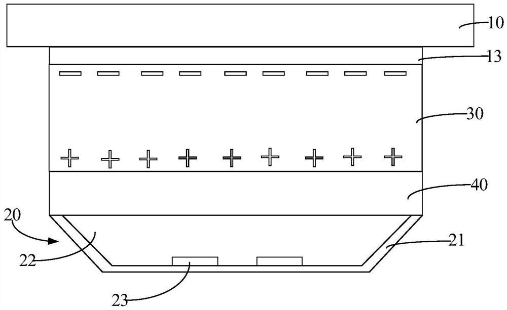
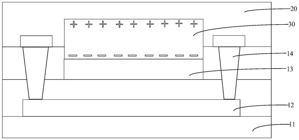
The invention provides a transfer mechanism used for transferring a miniature light-emitting element. The transfer mechanism comprises a switch substrate and a transfer assembly, and the transfer assembly is arranged on the switch substrate. The transfer assembly comprises: a dielectric layer, wherein the dielectric layer is a flexible dielectric layer, and a cavity is formed in the dielectric layer; a transfer assembly arranged on the inner wall of the surface, facing the micro light-emitting element, of the cavity; and an elastic filling layer filled in the cavity body. Through the arrangement of the flexible dielectric layer and the elastic filling layer, the elastic filling layer can provide enough buffer space when the transfer assembly adsorbs the micro light-emitting element, so that the dielectric layer can be elastically deformed, the contact area of an uneven contact surface between the micro light-emitting element and the transfer mechanism is increased, therefore, the adsorption force between the micro light-emitting element and the transfer mechanism is increased, and the yield of the transfer mechanism in the process of transferring the micro light-emitting element is improved.

Description

technical field [0001] The present application relates to the technical field of display devices, in particular to a transfer mechanism. Background technique [0002] Micro-LED (Micro-LED) or Mini LED (Mini LED) display technology uses micro-light-emitting elements of 1 micron to 100 micron (μm) as the pixel unit of the display. Compared with LCD and OLED display technologies, it has high quantum Efficiency, high contrast, high viewing angle, high color gamut, extremely fast response time, easy to use as transparent display, long life and other outstanding advantages will gradually become the mainstream technology of the next generation of displays. [0003] In the manufacturing process of Micro or Mini LED display devices, the key process is to accurately and quickly transfer single or cut small-sized micro-light-emitting elements with micro-light-emitting elements to the display substrate. When a large number of micro light-emitting elements can be transferred in one tran...

Claims


Application Information

Patent Timeline
IPC IPC(8): H01L21/67H01L21/683H01L33/00
CPCH01L33/0093H01L21/6833H01L21/67138
Inventor 胡琛卢马才
Owner SHENZHEN CHINA STAR OPTOELECTRONICS SEMICON DISPLAY TECH CO LTD
Learn More