Sequential model prediction control method for reducing switching loss of grid-connected inverter

A model predictive control and switching loss technology, applied in AC network circuits, output power conversion devices, and AC power input into DC power output, etc. It can solve problems such as uncertainty, complex design process, and algorithm limitations. Achieve the effect of improving output efficiency, reducing switching loss, and reducing the number of cycles

Pending Publication Date: 2021-12-03
UNIV OF ELECTRONIC SCI & TECH OF CHINA +1
View PDF0 Cites 0 Cited by
  • Summary
  • Abstract
  • Description
  • Claims
  • Application Information

AI Technical Summary

Problems solved by technology

When reducing the loss based on the SVPWM algorithm, it is necessary to analyze the amplitude and phase of the corresponding current during modulation, and the design process is complicated
In addition, if multi-objective optimization (such as: current quality, midpoint voltage balance, filter resonance suppression) is performed on the T-type three-level on this basis, the algorithm for changing the modulation will be limited
Using the traditional MPC algorithm to reduce the loss, although the process is simple, but the traditional MPC controller involves the design of multiple weight factors, this process is complex and full of uncertainty
For the T-type three-level grid-connected inverter system under the active damping filter, it is necessary to consider the four objectives of grid-connected current quality, midpoint voltage balance, active damping filter resonance peak suppression, and inverter loss, then At least three weighting factors need to be designed, which is a very challenging process

Method used


Image

  • Sequential model prediction control method for reducing switching loss of grid-connected inverter
  • Sequential model prediction control method for reducing switching loss of grid-connected inverter
  • Sequential model prediction control method for reducing switching loss of grid-connected inverter

Examples


Embodiment Construction

[0060] The technical solution will be clearly and completely described below in conjunction with preferred examples of the present invention and accompanying drawings. It should be understood that the preferred examples are only for illustrating the present invention, but not for limiting the protection scope of the present invention. Based on the embodiments of the present invention, all other embodiments obtained by persons of ordinary skill in the art without making creative efforts belong to the protection scope of the present invention.

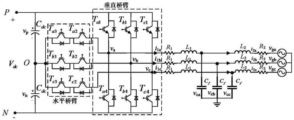
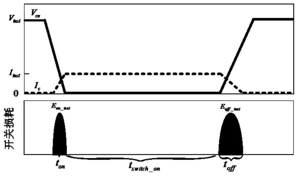
[0061] The invention provides a multi-objective optimization control strategy for reducing the switching loss of a T-type three-level LCL type grid-connected inverter. Through the analysis of the current path changes brought about by the switching state transition under different directions of the inverter output current, the switching loss model of the inverter is established. In the switching loss model, based on the switching state at...


PUM


Abstract

In order to reduce the switching loss of a T-type three-level LCL-type grid-connected inverter and realize multi-objective optimization of the inverter, sequential model prediction control is adopted. According to a sequential model prediction control method, a switching loss model of a T-type three-level inverter is established based on analysis of an output current path of the inverter under different switching state conversion. In order to reduce the number of weight factors when multi-objective optimization is realized by utilizing predictive control, cost functions of all levels are distributed for midpoint potential balance, current (grid side and inverter side), capacitor voltage tracking error and switching loss by adopting sequential model predictive control, and enter a three-layer prediction controller in sequence according to the priorities of the four optimization targets, so as to obtain a comprehensive optimal switching vector as a driving signal of the inverter. According to the sequential model prediction control method, the switching loss of the inverter is greatly reduced, the system efficiency is improved, and meanwhile, the neutral-point potential balance, resonance peak suppression and high-quality grid-side current output performance are ensured.

Description

technical field [0001] The invention belongs to the technical field of reducing the switching loss of a grid-connected inverter, and in particular relates to a sequential model predictive control method for reducing the switching loss of a grid-connected inverter. Background technique [0002] At present, distributed power generation systems based on new energy sources need to use grid-connected inverters to invert DC power into AC power that meets grid-connected requirements. T-type three-level inverter has been more and more used in engineering because of its high-quality current output performance and lower conduction loss in medium and low voltage systems. Compared with the traditional diode NPC topology, the T-type three-level inverter does not need to add diodes to clamp the midpoint voltage, which not only reduces the volume of the inverter, but also improves the system reliability. In addition, since the active damping LCL filter can avoid the use of filter resistor...

Claims


Application Information

Patent Timeline
IPC IPC(8): H02J3/18H02M7/487
CPCH02J3/1842H02M7/487Y02E40/30
Inventor 龙波沈大为曹天旭齐欣越
Owner UNIV OF ELECTRONIC SCI & TECH OF CHINA
Why Eureka
Try Eureka