
Process for laser cladding of nickel-based alloy powder on copper alloy primary mold glass mold

A laser cladding and glass mold technology, applied in metal material coating process, coating and other directions, can solve the problems of uncontrollable welding layer width, low qualification rate, large amount of powder, etc., to ensure product quality consistency and Stability, ensuring consistency and yield, reducing scrap and rework

Pending Publication Date: 2021-12-07
江苏智远激光装备科技有限公司
View PDF0 Cites 0 Cited by
  • Summary
  • Abstract
  • Description
  • Claims
  • Application Information

AI Technical Summary

Problems solved by technology

At the same time, during the repeated mold opening and closing process of the glass mold, due to impact and extrusion, the seam line, upper and lower joints of the mold will be damaged and rough, which will affect the quality of the glass product. Therefore, according to the characteristics of the use environment of the glass mold, In order to improve its service life and the quality of glass products, it is necessary to strengthen the corresponding position of the glass mold to improve its high temperature resistance, wear resistance, oxidation resistance and thermal fatigue resistance.
[0003] Traditional glass mold performance strengthening methods include: manual arc surfacing, manual flame spray welding, plasma surfacing, etc. Although these methods and methods can complete the strengthening of glass molds, there are many shortcomings in manual surfacing and spray welding: for example, Low welding layer bonding, low manual operation efficiency, poor quality consistency, large amount of powder, etc.
Due to the small volume of the die, small weld bead, large input volume and high dilution rate of the plasma stack, it is easy to crack and porosity when the copper alloy die is surfacing, and the pass rate is extremely low
At present, the main method of copper alloy die strengthening is manual spray welding, which has low efficiency and cannot control the width of the weld layer, and can only carry out large-area and thick full-spray welding of the inner cavity of the die, resulting in a huge material loss. waste

Method used


Image

  • Process for laser cladding of nickel-based alloy powder on copper alloy primary mold glass mold
  • Process for laser cladding of nickel-based alloy powder on copper alloy primary mold glass mold
  • Process for laser cladding of nickel-based alloy powder on copper alloy primary mold glass mold

Examples


Embodiment 1

[0029] Taking laser cladding of a copper alloy beer bottle mold (primary mold) as an example, a specific implementation method of laser cladding nickel-based alloy powder process for a copper alloy primary mold glass mold is described. The steps are as follows:

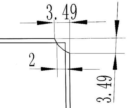
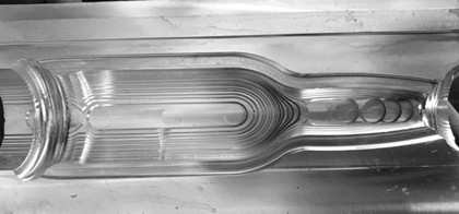
[0030] A) Cavity pre-processing, turning and milling on the joint surface of the mold and the upper and lower interface models, milling out the welding groove, controlling the size of the groove, and obtaining the workpiece to be laser cladding. In this example, the seam line, the upper and lower interface weld grooves and their dimensions are as follows: figure 1 , 2 shown. The initial mold workpiece after grooving is as follows: image 3 shown.

[0031] B) Pre-treatment of laser cladding: Clean the welding groove of the workpiece to be laser cladding, remove burrs and oil stains.

[0032] C) Import the 3D model of the glass mold into the Robotmaster offline programming software, model and generate a cladding tra...

Embodiment 2

[0036] Taking the laser cladding of the die as an example, a specific implementation method of the laser cladding nickel-based alloy powder process for the glass mold of the copper alloy primary mold is described, and the steps are as follows:

[0037] A) Cavity processing: the same requirements as in Example 1, the die is processed, and the slots obtained are as follows Figure 5 shown.

[0038] B) Pre-treatment of laser cladding: same as Example 1.

[0039] C) Import the 3D model of the glass mold into the Robotmaster offline programming software, model and generate a cladding trajectory program, and then download it to the robot system for teaching programming.

[0040]D), Laser cladding: The equipment used is the same as the example, the process parameters are: the focal spot is φ3.5mm, the working distance of the powder feeding nozzle of the cladding head is 21mm, the laser output power is 2600W, and the powder feeding amount is 25g / min. The protective gas used is: argo...


PUM

PropertyMeasurementUnit
Thicknessaaaaaaaaaa
Thicknessaaaaaaaaaa

Abstract

The invention relates to a process for laser cladding of nickel-based alloy powder on a copper alloy primary mold glass mold. The process comprises the following steps that a cavity is pre-machined, and specifically, welding grooves are formed in the forming mold and primary mold joint surfaces and upper and lower connectors of the mold in a turn-milling mode according to requirements; pre-treatment is conducted, and specifically, burrs and greasy dirt in the groove openings are cleaned through a brush; track programming is conducted by adopting off-line programming software to generate a motion track program; laser cladding is conducted, specifically, technological parameters are set, laser cladding is conducted along a cladding groove, so that the problem that cracks and air holes are prone to being generated due to laser cladding of the nickel-based alloy powder on the copper alloy glass mold is solved, and the main problems of traditional manual spray welding and plasma surfacing are solved; the nickel-based alloy strengthening of the joint surfaces and the connectors of the copper alloy mouth mold, which cannot be completed by plasma surfacing, is realized; and the working procedures of preheating, heat preservation, annealing and the like in traditional technological means such as plasma surfacing are omitted, and compared with manual spray welding and plasma surfacing, the powder consumption is greatly reduced, the production efficiency and the product quality qualification rate are remarkably improved, and the production cost is saved.

Description

technical field [0001] The invention relates to the field of glass mold processing and manufacturing, in particular to a process of laser cladding nickel-based alloy powder on a copper alloy primary glass mold, which is suitable for processing and manufacturing copper alloy glass molds (molding and primary molds). Background technique [0002] In the manufacturing process of glass products, the temperature of the molten glass water is as high as 1100°C, and the glass mold has been in contact with high-temperature glass water for a long time, which requires high temperature resistance and good oxidation resistance. At the same time, during the repeated mold opening and closing process of the glass mold, due to impact and extrusion, the seam line, upper and lower joints of the mold will be damaged and rough, which will affect the quality of the glass product. Therefore, according to the characteristics of the use environment of the glass mold, In order to improve its service l...

Claims


Application Information

Patent Timeline
IPC IPC(8): C23C24/10C22C19/05
CPCC23C24/106C22C19/058
Inventor 林学春农光壹林培晨谭长伟杭骏祥马建华
Owner 江苏智远激光装备科技有限公司
Learn More