Metal ion source and application and use method thereof

A metal ion source and ion technology, applied in the field of metal ion sources, can solve the problems of limited wall thickness of the cathode tube, lack of metal ions, and small sputtering area, so as to avoid large-area discharge, improve the bonding force of the film base, and prevent sputtering. The effect of large shot area

Active Publication Date: 2021-12-07
XIHUA UNIV
View PDF7 Cites 0 Cited by
  • Summary
  • Abstract
  • Description
  • Claims
  • Application Information

AI Technical Summary

Problems solved by technology

This technology usually requires the supply of metal ions. As far as tubular parts are concerned, if the metal is supplied as a metal gas phase compound, there must be a concentration difference between the supply inlet port and the outlet port, so that the modified layer is not uniform.
Technologies such as plasma immersion ion implantation first generate metal ions on the outside, and then allow the metal ions to diffuse into the tubular part. This technology still has a concentration difference, which makes the distribution of the modified layer in the axial direction uneven.
[0003] CN 108456862 B grooves on the cathode tube wall, although the hollow cathode discharge can be formed in the direction perpendicular to the inner surface, but due to the limitation of the space position, the wall thickness of the cathode tube is limited, and the sputtering area is small, resulting in relatively low sputtering efficiency. Low, difficult to get engineering application
[0004] Therefore, the modification of the inner surface of elongated tubes has been a difficult problem in the field of plasma surface modification due to the lack of efficient and controllable supply of metal ions.

Method used


Image

  • Metal ion source and application and use method thereof
  • Metal ion source and application and use method thereof
  • Metal ion source and application and use method thereof

Examples


Embodiment 1

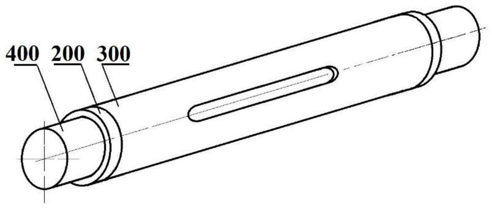
[0057] refer to figure 1 , figure 2 and image 3 As shown, the present embodiment provides a source of metal ions. It includes an outer core 100 serving as an anode, an insulating base 200 , a shield tube 300 and a cathode 400 . Wherein, the shielding tube 300 is arranged around the outside of the cathode (inner core) 400, and the cathode 400 is provided with a through hole 410 with a width of 5-10mm.

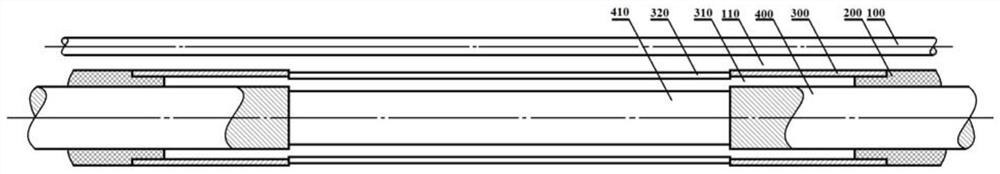
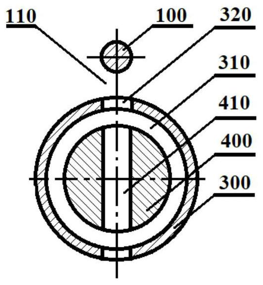
[0058] refer to figure 2 and image 3 As shown, the shielding tube 300 is arranged between the cathode 400 and the outer core 100, the inner peripheral wall of the shielding tube 300 and the outer peripheral wall of the cathode 400 form a first gap 310, and a second gap is formed between the outer peripheral wall of the shielding tube 300 and the outer core 100 110.

[0059] Two ion passage holes 320 are opened on the side wall of the shielding tube 300; among them, the through hole 410 and the ion passage hole 320 have the same shape, the same axial size, and the same ...

Embodiment 2

[0075] This embodiment provides a titanium ion source, and the only difference from Embodiment 1 is that the through hole 410 and the ion through hole 320 of the titanium ion source in this embodiment are all set as spiral holes with a pitch of 150 mm along the right helical line. , The cathode 400 is made of pure titanium.

Embodiment 3

[0077] The present embodiment provides a kind of tungsten ion source, and its only difference with embodiment 1 is: refer to Figure 4 As shown, in the present embodiment, the outer core 100 is a part to be processed, which has a hole with a diameter of 100mm and a length of 3500mm, and the shielding tube 300 is a tungsten tube with an inner diameter of 80mm, a wall thickness of 3mm, and a length of 3000mm;

[0078] Four ion passage holes 320 are opened in the middle of the shielding tube 300 in the axial direction, each ion passage hole 320 is 8mm wide and 2000mm long, and is evenly arranged along the circumference;

[0079] The cathode 400 is made of a tungsten rod with a diameter of 72 mm and a length of 3000 mm. Two through holes 410 are uniformly arranged in the middle of the cathode 400. Each through hole 410 is 8 mm wide and 2000 mm long, and is evenly arranged along the circumference. The angle between the two through holes 410 is 90 degrees. After the two ends of the ...


PUM

PropertyMeasurementUnit
widthaaaaaaaaaa

Abstract

The invention discloses a metal ion source and application and a use method thereof, and relates to the technical field of surface engineering. The device comprises an inner core used as a cathode, an outer core used as an anode and a shielding tube. The metal ion source provided by the invention has relatively high sputtering efficiency, metal ions can be uniformly supplied in the tubular part along the axial direction, and a uniform surface modification layer can be conveniently obtained on the inner surface; the through holes are formed in the two sides of the inner core, so that the metal ion sputtering area is larger, and the sputtering efficiency is higher. And the outer core is independently arranged outside the shielding tube, so that the miniaturization of the overall structure of the metal ion source is facilitated. Therefore, the inner surface of a smaller tubular workpiece is modified, the application range is wider, the structure is simplified to a great extent, and the reliability is improved. In addition, the invention also provides a use method and application of the metal ion source.

Description

technical field [0001] The invention relates to the technical field of surface engineering, in particular to a metal ion source and its application and usage method. Background technique [0002] Plasma surface modification technology has the advantages of simple process, fast processing speed and good treatment effect, and has been widely used at present. This technology usually requires the supply of metal ions. As far as tubular parts are concerned, if the metal is supplied as a metal gas phase compound, there must be a concentration difference between the supply inlet port and the outlet port, so that the modified layer is not uniform. Technologies such as plasma immersion ion implantation first generate metal ions on the outside, and then allow the metal ions to diffuse into the tubular part. This technology still has a concentration difference, which makes the distribution of the modified layer in the axial direction uneven. [0003] CN 108456862 B grooves on the cath...

Claims


Application Information

Patent Timeline
Patent Type & Authority Applications(China)
IPC IPC(8): H01J37/32C23C14/34
CPCH01J37/32412H01J37/32596C23C14/34H01J2237/3365
Inventor 刘锦云金应荣贺毅曹仁发王梦嘉曾国兴张平万海毅
Owner XIHUA UNIV
Why Eureka
Try Eureka