High-temperature superconducting energy storage monitoring system

A monitoring system, superconducting energy storage technology, applied in the direction of superconducting magnets/coils, secondary battery testing, magnetic objects, etc., can solve the lack of real-time monitoring of power source data, accelerated degradation of power battery performance, and impact on battery life cycle, etc. problem, to avoid frequent charging and discharging, shorten the time, and avoid the effect of extreme discharge impact

Pending Publication Date: 2021-12-07
SHANGHAI MARITIME UNIVERSITY
View PDF5 Cites 0 Cited by
  • Summary
  • Abstract
  • Description
  • Claims
  • Application Information

AI Technical Summary

Problems solved by technology

[0005] Based on this, it is necessary to solve the problem that the traditional power battery cannot release enough electric energy in a short time, the extreme discharge shock causes the performance of the power battery to decline rapidly, frequent charging and discharging affects the life cycle of the battery, and traditional electric vehicles lack real-time monitoring of power source data. The problem is to provide a high-temperature superconducting energy storage monitoring system that can release a large amount of electric energy in a short period of time, alleviate the impact of the ultimate discharge impact on the power battery, reduce the charging and discharging frequency of the power battery, and monitor power source data in real time.

Method used


Image

  • High-temperature superconducting energy storage monitoring system
  • High-temperature superconducting energy storage monitoring system
  • High-temperature superconducting energy storage monitoring system

Examples


Embodiment Construction

[0022] In order to make the purpose, technical solutions and advantages of the embodiments of the present invention more clear, the technical solutions in the embodiments of the present invention will be clearly and completely described below in conjunction with the accompanying drawings in the embodiments of the present invention. Obviously, the described embodiments It is a part of embodiments of the present invention, but not all embodiments. Based on the embodiments of the present invention, all other embodiments obtained by persons of ordinary skill in the art without making creative efforts belong to the protection scope of the present invention.

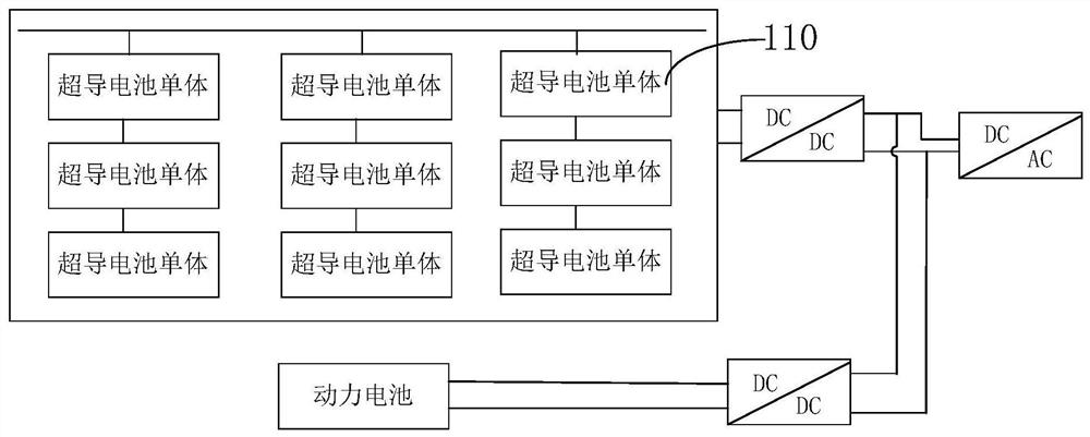
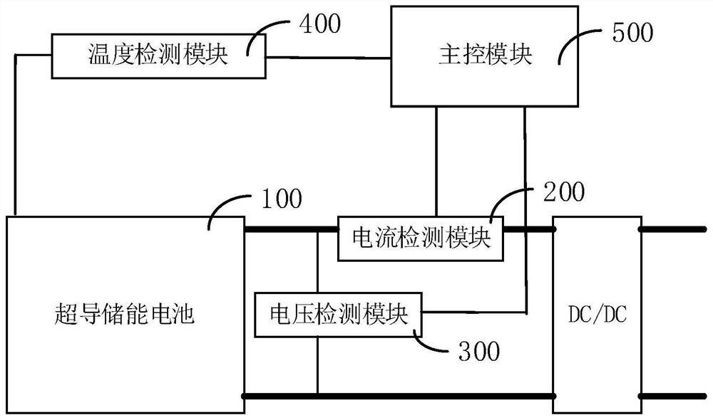
[0023] Such as figure 1 and figure 2 As shown, in one embodiment, a high temperature superconducting energy storage monitoring system includes a superconducting energy storage battery 100, a current detection module 200, a voltage detection module 300 and a main control module 500;

[0024] The superconducting energy storag...


PUM


Abstract

The invention relates to a high-temperature superconducting energy storage monitoring system. The system comprises a superconducting energy storage battery, a current detection module, a voltage detection module and a main control module; the superconducting energy storage battery is electrically connected with a vehicle power battery and a vehicle driving motor; the current detection module and the voltage detection module are respectively electrically connected with the superconducting energy storage battery and are respectively used for detecting the output voltage and the output current of the superconducting energy storage battery; the main control module is connected with the current detection module and the voltage detection module, and is used for obtaining and processing the output voltage and the output current, and displaying the voltage value and the current value. According to the high-temperature superconducting energy storage monitoring system, the current detection module and the voltage detection module are installed on the superconducting energy storage battery and used for detecting signals such as current and voltage of the superconducting energy storage battery in real time, so that the state of the superconducting energy storage battery is regulated and controlled in time, and the stability and reliability of the superconducting energy storage battery are improved.

Description

technical field [0001] The invention relates to the technical field of energy storage, in particular to a high-temperature superconducting energy storage monitoring system. Background technique [0002] With the rapid development of electric vehicles and other electric vehicles, electrochemical batteries such as lithium-ion batteries have become the fastest-growing and most widely used energy storage methods. Transportation systems usually require high-energy energy storage devices to achieve long-term battery life through long-term discharge, thereby maximizing system efficiency and minimizing system cost and mass. [0003] In the starting or accelerating stage of electric vehicles, the power battery needs to be discharged quickly to provide sufficient power. However, due to the limitation of the structure and performance of the traditional power battery itself, the discharge speed is slow, and it cannot release enough electric energy in a short period of time, resulting i...

Claims


Application Information

Patent Timeline
Patent Type & Authority Applications(China)
IPC IPC(8): H01M10/42H01M10/48H01F6/06
CPCH01M10/48H01M10/4285H01F6/06Y02E60/10
Inventor 杨平毛寿祺马琳高迪驹刘志全周贤文杜永强
Owner SHANGHAI MARITIME UNIVERSITY
Why Eureka
Try Eureka