
A galvanometer laser stitch welding equipment

A laser and equipment technology, applied in the field of galvanometer laser stitch welding equipment, can solve problems such as high reflectivity, laser reflection, and affecting laser stitch welding efficiency, and achieve the effects of improving smoothness, reducing friction, and improving welding efficiency

Active Publication Date: 2022-02-08
张家港汇能达激光科技有限公司
View PDF0 Cites 0 Cited by
  • Summary
  • Abstract
  • Description
  • Claims
  • Application Information

AI Technical Summary

Problems solved by technology

[0003] Existing laser stitch welding refers to laser welding after one workpiece is superimposed on the surface of another workpiece. For example, the stitch welding of pipes is to socket a pipe with a smaller diameter inside a pipe with a larger diameter and then weld it. Some existing tubular The surface of the workpiece is relatively smooth and has a high reflectivity to light. At this time, when the laser is irradiated on the surface for welding, part of the laser will be reflected, which will affect the efficiency of laser stitch welding.

Method used


Image

  • A galvanometer laser stitch welding equipment
  • A galvanometer laser stitch welding equipment
  • A galvanometer laser stitch welding equipment

Examples


Embodiment Construction

[0032] The following will clearly and completely describe the technical solutions in the embodiments of the present invention with reference to the accompanying drawings in the embodiments of the present invention. Obviously, the described embodiments are only some, not all, embodiments of the present invention. Based on the embodiments of the present invention, all other embodiments obtained by persons of ordinary skill in the art without making creative efforts belong to the protection scope of the present invention.

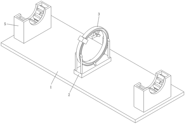
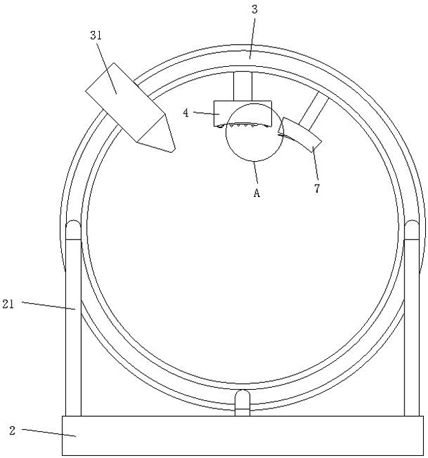
[0033] see Figure 1-7, the present invention provides a technical solution: a galvanometer laser stitching welding equipment, including a bottom plate 1, a sliding mounting seat 2 is fixed at the center of the top of the bottom plate 1, and the top of the sliding mounting seat 2 is fixed to the bottom ends of three fixed sliding rods 21. The other end of the sliding rod 21 is slidingly connected to the side of the rotating welding ring 3, and the three fixed ...


PUM


Abstract

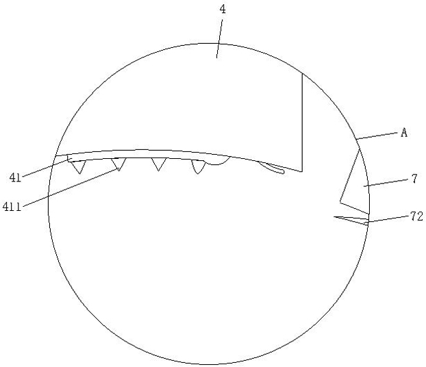
The invention discloses a vibrating mirror laser stitching welding equipment, which relates to the technical field of laser stitching welding. The galvanometer laser stitching welding equipment includes a bottom plate, a sliding mounting seat is fixed at the center of the top of the bottom plate, the top of the sliding mounting seat is fixed to the bottom ends of three fixed sliders, and the other end of the fixed sliders slides with the side of the rotating welding ring connected, and the three fixed slide bars are respectively located at the center of the front and rear parts and the center of the bottom of the side of the rotary welding ring. The galvanometer laser stitch welding equipment can make the laser head weld around the tubular workpiece by setting the rotating welding ring, without rotating the workpiece during the welding process, and can avoid the dislocation and disconnection of the welded points on the surface of the workpiece during the rotation process. At the same time, setting the friction plate can use the rotation of the rotating welding ring to describe the welding place of the tubular workpiece, so that scratches appear on the surface of the workpiece, making the surface of the workpiece rougher, so as to reduce the reflection effect of the workpiece surface on the laser.

Description

technical field [0001] The invention relates to the technical field of laser stitch welding, in particular to a galvanometer laser stitch welding equipment. Background technique [0002] Laser welding is an efficient and precise welding method that uses a high-energy-density laser beam as a heat source. Laser welding is one of the important aspects of the application of laser material processing technology. The welding process is of heat conduction type, that is, the laser radiation heats the surface of the workpiece, and the surface heat diffuses to the interior through heat conduction. By controlling the width, energy, peak power and repetition frequency of the laser pulse, etc. parameters to melt the workpiece to form a specific molten pool. [0003] Existing laser stitch welding refers to laser welding after one workpiece is superimposed on the surface of another workpiece. For example, the stitch welding of pipes is to socket a pipe with a smaller diameter inside a pip...

Claims


Application Information

Patent Timeline
Patent Type & Authority Patents(China)
IPC IPC(8): B23K26/21B23K26/70B23P23/00
CPCB23K26/21B23K26/70B23K26/702B23P23/00
Inventor 任云鹏
Owner 张家港汇能达激光科技有限公司
Learn More