
Wood board drilling equipment

A technology for drilling equipment and wood boards, which can be applied to fixed drilling machines and other directions, can solve problems such as drilling, and achieve the effects of increasing usage rate, good pressing effect and high precision

Active Publication Date: 2021-12-10
吉屋(青岛)家居有限公司
View PDF16 Cites 1 Cited by
  • Summary
  • Abstract
  • Description
  • Claims
  • Application Information

AI Technical Summary

Problems solved by technology

[0005] In order to overcome the traditional method of drilling wood boards, the manual hand-held drilling machine is generally used to drill holes on the boards. The manual operation is relatively random and it is difficult to accurately drill holes on the boards. The technical problem of the present invention is to provide a A kind of wood drilling equipment with more accurate drilling and pressing function

Method used


Image

  • Wood board drilling equipment
  • Wood board drilling equipment
  • Wood board drilling equipment

Examples


Embodiment 1

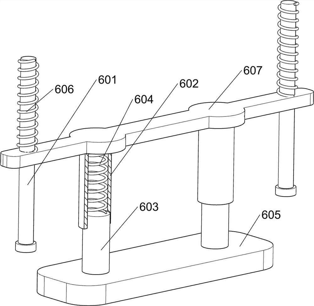
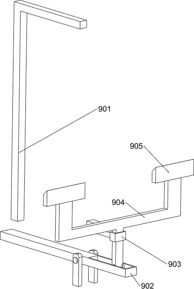
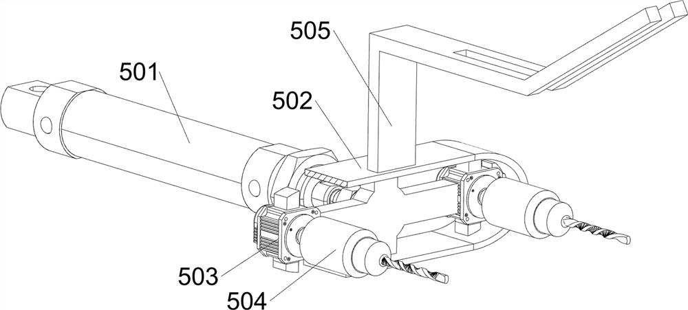
[0027] A device for drilling holes in wood, such as figure 1 , figure 2 , image 3 with Figure 4 As shown, it includes a base 1, a bracket 2, a workbench 3, a drill bit 4, a drive assembly 5 and a pressing assembly 6, the top right side of the base 1 is symmetrically provided with a bracket 2, the top right side of the base 1 is provided with a workbench 3, and the base 1. A driving assembly 5 is provided on the left side of the top, and a drill bit 4 is arranged symmetrically on the driving assembly 5. A pressing assembly 6 is provided on the right side of the upper part of the workbench 3. The driving assembly 5 cooperates with the pressing assembly 6.

[0028] When people need to drill a plank, they place the plank on the workbench 3, then start the drive assembly 5, and under the action of the drive assembly 5, the drill bit 4 is driven to drill the plank, while the pressing assembly 6 pairs The planks are compressed, which can make it easier for the planks to carry o...

Embodiment 2

[0033] On the basis of Example 1, such as figure 2 , Figure 5 , Image 6 with Figure 7 As shown, a feed assembly 7 is also included, and the feed assembly 7 includes a first rack 701, a rotating shaft 702, a gear 703, a first guide groove 704, a push rod 705, a second rack 706, and a second guide rod 707, feed frame 708 and the 3rd spring 709, support sleeve 502 front and rear sides are provided with first tooth bar 701, and workbench 3 upper left side symmetrical rotation type is provided with rotating shaft 702, is all provided with gear 703 on rotating shaft 702, gear 703 are all meshed with the first rack 701, and the inner side of the upper part of the bracket 2 is provided with a first guide groove 704, between the first guide grooves 704, a pusher rod 705 is slidingly provided, and the bottom of the pusher rod 705 is symmetrically provided with a fixed block, The two ends on the left side of the push rod 705 are provided with a second rack 706, and the second rack...


PUM


Abstract

The invention relates to drilling equipment, and especially relates to wood board drilling equipment. The technical problem of the invention is to provide the wood board drilling equipment which is accurate in drilling and has a pressing function. The technical implementation scheme of the invention is as follows: the wood board drilling equipment comprises a base, supports, a workbench, a driving assembly, drill bits and a pressing assembly, wherein the supports are symmetrically arranged at one side of the top of the base; the workbench is arranged at one side of the top of the base; the driving assembly is arranged at the other side of the top of the base; the drill bits are symmetrically arranged on the driving assembly; and the pressing assembly is arranged at one side of the workbench, and the driving assembly is cooperated with the pressing assembly. According to the invention, under the action of the driving assembly, the drill bits are driven to drill a wood board, meanwhile, the wood board is pressed by the pressing assembly, the wood board can be more conveniently drilled, a good pressing effect of the pressing assembly is achieved, the wood board can be more stably drilled, and high drilling precision is achieved.

Description

technical field [0001] The invention relates to a drilling device, in particular to a wood drilling device. Background technique [0002] At present, a large number of wood boards are used in our lives. Wood boards are closely related to each of us. Some buildings, interior furniture, interior decoration, etc. will use wood boards. [0003] In the process of wood processing, especially the processing of wood boards, according to people's needs, the wood boards are drilled. The traditional way of drilling wood boards is generally to use manual hand-held drilling machines to drill holes on the boards. Personal factors, manual operation is more casual, it is difficult to accurately drill holes on the wooden board, so that the accuracy of the wooden board drilling is low, affecting the drilling quality of the wooden board, and the drilling speed is slow, which greatly reduces people's work efficiency There are many other problems. [0004] To sum up, it is necessary to design ...

Claims


Application Information

Patent Timeline
Patent Type & Authority Applications(China)
IPC IPC(8): B27C3/04
CPCB27C3/04Y02P70/10
Inventor 黄莺
Owner 吉屋(青岛)家居有限公司
Learn More