Cooling system and wind generating set

A cooling system and cooling circuit technology, which is applied in wind turbines, wind power generation, cooling/ventilation devices, etc., can solve the problems of complex cooling system composition and layout, achieve balanced utilization, realize reasonable application, and reduce system power consumption Effect

Pending Publication Date: 2021-12-10
XINJIANG GOLDWIND SCI & TECH
View PDF0 Cites 2 Cited by
  • Summary
  • Abstract
  • Description
  • Claims
  • Application Information

AI Technical Summary

Problems solved by technology

Generators, shafting, pitch, engine room cabinets, engine rooms, converter cabinets, transformers and other heat-generating components all need to undergo necessary heat dissipation and cooling treatment to realize the normal operation of each heat-generating component, especially for offshore wind turbines. The components are all arranged in the E-TOP structure of the engine room, which makes the composition and layout of the overall cooling system in the engine room more and more complicated

Method used


Image

  • Cooling system and wind generating set
  • Cooling system and wind generating set
  • Cooling system and wind generating set

Examples


Embodiment Construction

[0037] Features and exemplary embodiments of various aspects of the invention will be described in detail below. In the following detailed description, numerous specific details are set forth in order to provide a thorough understanding of the present invention. It will be apparent, however, to one skilled in the art that the present invention may be practiced without some of these specific details. The following description of the embodiments is only to provide a better understanding of the present invention by showing examples of the present invention. In the drawings and the following description, at least some well-known structures and techniques have not been shown in order to avoid unnecessarily obscuring the present invention; and, for clarity, the dimensions of some structures may have been exaggerated. Furthermore, the features, structures, or characteristics described hereinafter may be combined in any suitable manner in one or more embodiments.

[0038] The orient...


PUM


Abstract

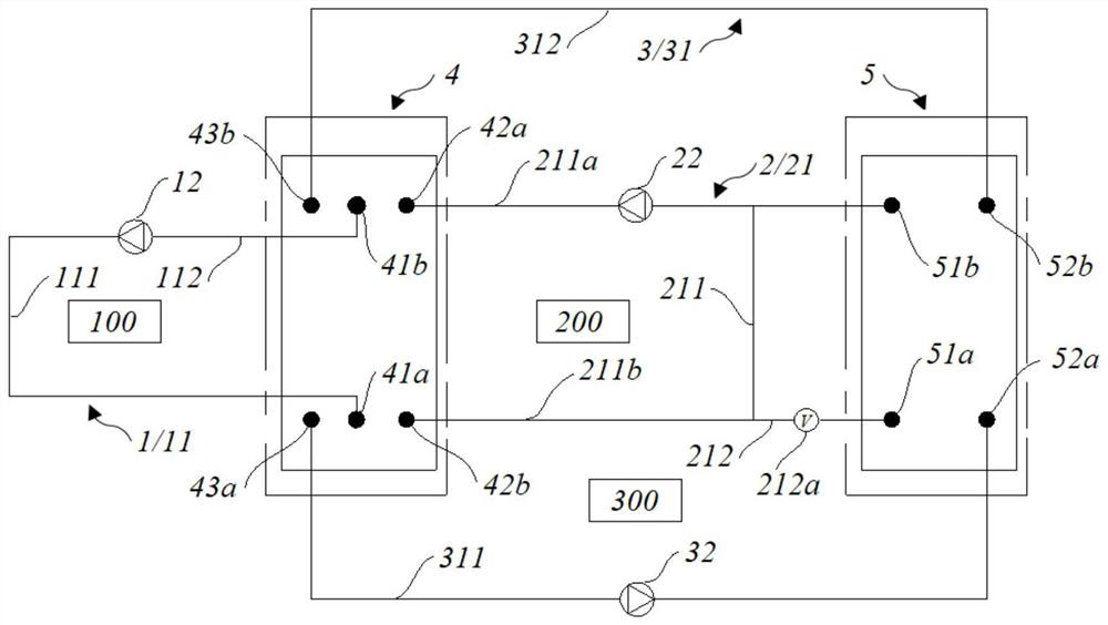
The invention relates to a cooling system and a wind generating set. The cooling system comprises a first cooling loop, a second cooling loop, a third cooling loop, a first heat exchanger and a second heat exchanger, the first cooling loop comprises a first fluid pipeline and a first pump set, the second cooling loop comprises a second fluid pipeline and a second pump set, and the second fluid pipeline comprises a main path and a bypass; and the third cooling loop comprises a third fluid pipeline and a third pump set. The third fluid pipeline is communicated with the first heat exchanger and the second heat exchanger at the same time. The first heat exchanger is configured to enable a first cooling medium, a second cooling medium and a third cooling medium to be thermally coupled in a mutual isolation manner; and the second heat exchanger is configured to thermally couple the second cooling medium and the third cooling medium in a mutual isolation manner via the bypass. Reasonable distribution of cooling capacity and reasonable application of waste heat are achieved through mutual-isolation thermal coupling between the cooling loops, so that balanced utilization of cold and heat is achieved, and power consumption of the system is reduced.

Description

technical field [0001] The invention relates to the technical field of wind power generation, in particular to a cooling system and a wind power generating set. Background technique [0002] In recent years, wind turbines have gradually developed towards high power density, and the loss of the wind turbine itself has increased accordingly, and the number of components that need to be dissipated has also increased. Generators, shafting, pitch, engine room cabinets, engine rooms, converter cabinets, transformers and other heat-generating components all need to undergo necessary heat dissipation and cooling treatment to realize the normal operation of each heat-generating component, especially for offshore wind turbines. The components are all arranged in the E-TOP structure of the engine room, which makes the composition and layout of the overall cooling system of the unit more and more complicated in the engine room. Therefore, it is necessary to design a more compact coolin...

Claims


Application Information

Patent Timeline
Patent Type & Authority Applications(China)
IPC IPC(8): F03D80/60H01F27/16H05K7/20H02K9/19
CPCF03D80/60H01F27/16H05K7/20927H05K7/20945H02K9/19Y02E10/72H02K7/1838F05B2260/20
Inventor 王丁会方涛李金梦
Owner XINJIANG GOLDWIND SCI & TECH
Why Eureka
Try Eureka