Radiant tube burner with high-temperature ejector and use method of radiant tube burner

A radiant tube and ejector technology, which is applied in the field of burners, can solve the problems of increasing air volume, not saving energy, and low flue gas ejection and return rate.

Pending Publication Date: 2021-12-10
BAOSTEEL ENG & TECH GRP
View PDF0 Cites 0 Cited by
  • Summary
  • Abstract
  • Description
  • Claims
  • Application Information

AI Technical Summary

Problems solved by technology

There are also some burners that add air ejection at the outlet of the heat exchanger, but the flue gas ejection return rate is not high, generally below 30%, because the combustion becomes unstable with the increase of

Method used


Image

  • Radiant tube burner with high-temperature ejector and use method of radiant tube burner
  • Radiant tube burner with high-temperature ejector and use method of radiant tube burner
  • Radiant tube burner with high-temperature ejector and use method of radiant tube burner

Examples


Embodiment 1

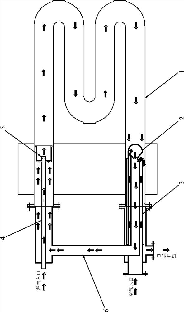
[0028] A tape high temperature radiant tube burner ejector, comprising a radiant tube 1, the high-temperature ejector 2, the heat exchanger 3, the burner body 4, the combustion burner head 5 and the communication pipe 6, as figure 1 and figure 2 , The specific configuration is:

[0029] Both ends of the radiant tube 1 are gas inlet and flue gas outlet;

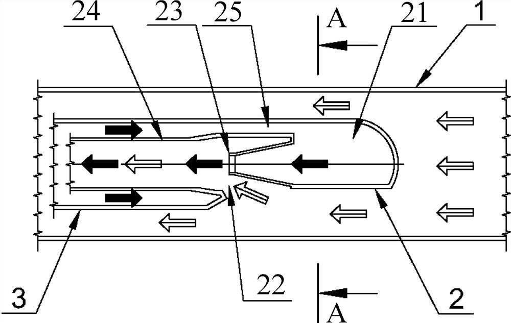
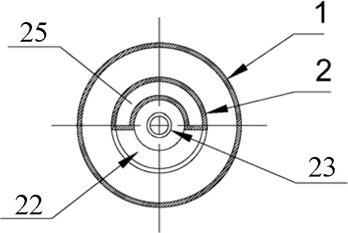
[0030] Temperature ejector 2 includes an air confluence chamber 21, gas ejector inlet channel 22, the air ejector nozzle 23, ejector mixing tube 24 and the air confluent passage 25, the air confluence chamber 21 the inlet end is larger than that connecting the air confluent passage 25 the area of ​​the outlet end, the inlet end of the air chamber 21 is connected confluent confluent air outlet end of the passage 25, the confluent air in the air chamber cavity 21 merging region other than the flue gas passage 25 constituting the ejector inlet channel 22, the air chamber 21 confluent an air outlet end the ejector nozzle 23, ejector m...


PUM


Abstract

The invention relates to the field of gas fuel combusting combustors with flame stabilizing devices, in particular to a radiant tube burner with a high-temperature ejector and a using method of the radiant tube burner. The radiant tube burner with the high-temperature ejector comprises a radiant tube (1) and is characterized by further comprising the high-temperature ejector (2), a heat exchanger (3), a burner body (4), a burner combustion spray head (5) and a communicating pipe (6), wherein the high-temperature ejector (2) comprises an air converging cavity (21), a flue gas ejection inlet channel (22), an air ejection nozzle (23), an ejection mixing pipe (24) and an air converging channel (25); and the burner combustion spray head (5) is arranged at one end of the burner body (4). The using method of the radiant tube burner with the high-temperature ejector is characterized by comprising the following steps: (1) air flow; (2) gas flow; and (3) heat exchange. The combustion is sufficient, the temperature distribution is uniform, and the emission of nitrogen oxides is reduced.

Description

Technical field [0001] FIELD The present invention relates to a burner having flame stabilizing means of burning gaseous fuels, in particular to a primer with a high temperature radiant tube burner ejector and method of use. Background technique [0002] With the improvement of the national environmental protection requirements, NO to the furnace flue gas emissions x (I.e., nitrogen oxide) emissions targets more and more attention in the field of metallurgical furnace, apparatus for heating the main burner, the main burner in a steel mill by-product gas can be referred to steel, comprising a blast furnace gas, coke oven gas, converter gas, wherein the mixed gas or coke oven gas most applications, the burner combustion products flue gas NO x One of the main indicators of environmental control. [0003] In the radiant tube burner type, because all combustion in the radiant tube, the combustion heat very high strength, resulting NO x Also the highest, at the same time, due to the li...

Claims


Application Information

Patent Timeline
IPC IPC(8): F23D14/04F23D14/12F23D14/26F23D14/46F23D14/48F23D14/64F23D14/66
CPCF23D14/04F23D14/12F23D14/26F23D14/46F23D14/48F23D14/64F23D14/66Y02E20/34
Inventor 李国杰王林建曾宪俊郑海薇刘方孙志斌沈权邓美玲
Owner BAOSTEEL ENG & TECH GRP
Why Eureka
Try Eureka