
Multifunctional touch all-in-one machine

An all-in-one, multi-functional technology, applied in the field of intelligent interaction, can solve the problems of reducing the service life of the touch all-in-one, damage to the touch all-in-one, discount of human-computer interaction feeling, etc., to achieve convenient movement, eliminate friction, The effect of removing limitations

Pending Publication Date: 2021-12-10
北京网格蔚来科技有限公司
View PDF0 Cites 0 Cited by
  • Summary
  • Abstract
  • Description
  • Claims
  • Application Information

AI Technical Summary

Problems solved by technology

But this kind of touch effect is very limited, and the effect on the entire display screen is not good, especially at the corners, the touch function is almost impossible to realize
In addition, infrared touch is prone to strong infrared interference, which will be affected by remote controls in the surrounding environment, daily lights, and sunlight
Moreover, it has received interference from strong electromagnetic objects, and because the chip processing infrared chip has a long replacement cycle, the speed is slow when processing occlusions, resulting in smearing, delay, or intermittent touch, which makes the feeling of human-computer interaction Big discount
[0003] Touch all-in-one machine is a machine that perfectly combines touch screen, LCD screen, industrial pc unit and all-in-one machine shell, and finally can realize touch operation through a power cord. However, when the existing touch all-in-one machine is in use, It will be impacted by external force, causing the touch all-in-one machine to shake, causing the touch all-in-one machine to move sideways and topple over, resulting in damage to the touch all-in-one machine and reducing the service life of the touch all-in-one machine

Method used


Image

  • Multifunctional touch all-in-one machine
  • Multifunctional touch all-in-one machine
  • Multifunctional touch all-in-one machine

Examples


Embodiment 1

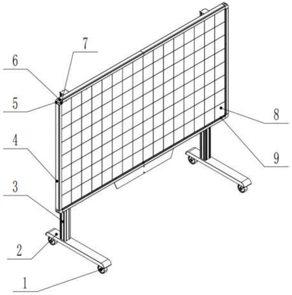
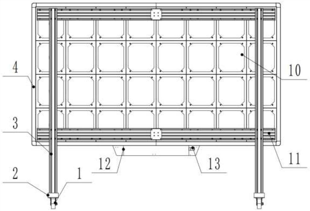
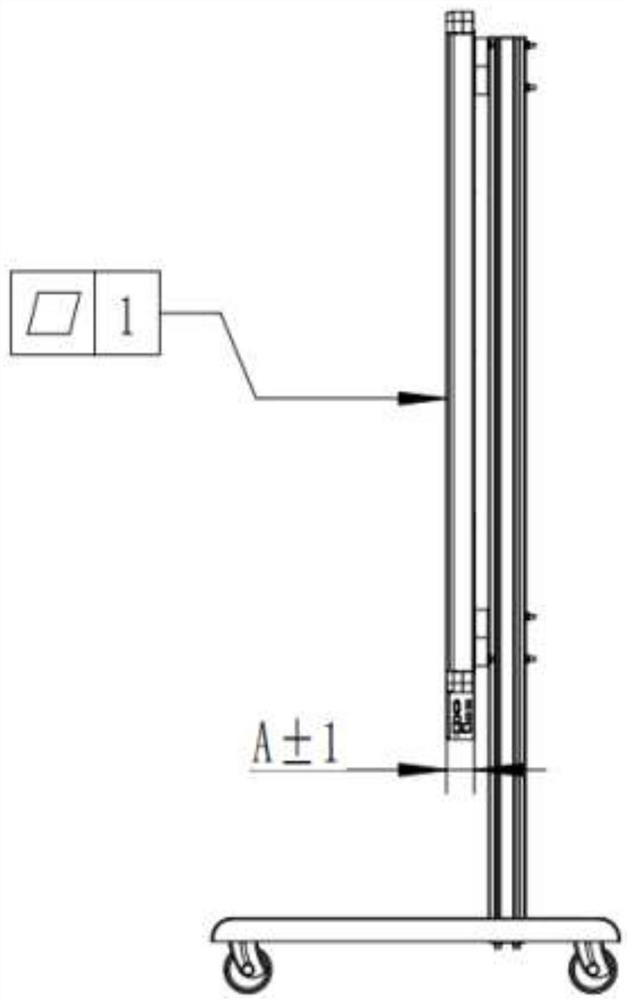
[0037] Embodiment one, by Figure 1-4Given, a multi-function touch all-in-one machine proposed by the present invention includes a support longitudinal beam 2, the bottom of the support longitudinal beam 2 is movably connected with an integral support universal wheel 1, and the number of the integral support universal wheel 1 is the support column 3 Twice the number, the support column 3 is symmetrically distributed on both sides of the touch combination frame 4, the optical camera 6 is used as a tool for capturing occlusions, and there is a reflective film of nearly 12mm around the screen body, which is completely covered and can adapt to different levels. High-definition screens, or non-luminous flat-screen devices, etc., more than three cameras are arranged around the screen to receive images reflected by the reflective film from multiple angles, and the signal processing is performed through the control board, and finally positioning is realized. The top of the beam 2 is f...

Embodiment 2

[0039] Embodiment two, by Figure 1-11 Given, a multi-function touch all-in-one machine proposed by the present invention includes a support longitudinal beam 2, the bottom of the support longitudinal beam 2 is movably connected with an integral support universal wheel 1, and the number of the integral support universal wheel 1 is the support column 3 Twice the number, the support column 3 is symmetrically distributed on both sides of the touch combination frame 4, the optical camera 6 is used as a tool for capturing occlusions, and there is a reflective film of nearly 12mm around the screen body, which is completely covered and can adapt to different levels. High-definition screens, or non-luminous flat-screen devices, etc., more than three cameras are arranged around the screen to receive images reflected by the reflective film from multiple angles, and the signal processing is performed through the control board, and finally positioning is realized. The top of the beam 2 is...

Embodiment 3

[0042] Embodiment three, by Figure 1-11 Given, a multi-function touch all-in-one machine proposed by the present invention includes a support longitudinal beam 2, the bottom of the support longitudinal beam 2 is movably connected with an integral support universal wheel 1, and the number of the integral support universal wheel 1 is the support column 3 Twice the number, the support column 3 is symmetrically distributed on both sides of the touch combination frame 4, the optical camera 6 is used as a tool for capturing occlusions, and there is a reflective film of nearly 12mm around the screen body, which is completely covered and can adapt to different levels. High-definition screens, or non-luminous flat-screen devices, etc., more than three cameras are arranged around the screen to receive images reflected by the reflective film from multiple angles, and the signal processing is performed through the control board, and finally positioning is realized. The top of the beam 2 ...


PUM


Abstract

The invention relates to the technical field of intelligent interaction, and discloses a multifunctional touch all-in-one machine which comprises a support longitudinal beam, the bottom of the support longitudinal beam is movably connected with an overall support universal wheel, the top of the support longitudinal beam is fixedly connected with a support stand column, and the outer side of the support stand column is fixedly connected with a support cross beam. The inner side of the support cross beam is slidably connected with a touch control combined frame. According to the multifunctional touch all-in-one machine, an optical camera is arranged, an optical camera rear cover and an optical camera front cover are arranged in a matched mode, an industrial camera is adopted for capturing images, the precision degree of the touch effect and the millisecond-level corresponding speed are greatly improved, the traditional infrared touch sensitivity is low, and in the practical application process, a phenomenon of shadow appears. More than three cameras are arranged on the periphery of a screen to receive images reflected by a reflective film in a multi-angle and omnibearing mode, signal processing is carried out through a control panel, and finally positioning is achieved.

Description

technical field [0001] The invention belongs to the field of intelligent interaction technology, and specifically relates to a multifunctional touch-control integrated machine. Background technique [0002] At present, in the field of intelligent interaction, the touch method is mainly used to realize the interaction. The touch method generally adopts infrared touch technology. The first choice requires a display screen. At present, the market is mainly an LCD screen, and then infrared emitting and receiving devices are installed around the plane. , and then continuously scan horizontally and vertically. When the touch object blocks the infrared light, the position is positioned to achieve the touch effect. However, this touch effect is very limited, and the effect on the entire display screen is not good, especially at the corners, and the touch function is almost impossible to realize. In addition, infrared touch is prone to strong infrared interference, which will be aff...

Claims


Application Information

Patent Timeline
Patent Type & Authority Applications(China)
IPC IPC(8): G06F3/041G06F1/16F16M11/04F16M11/24F16M11/42
CPCG06F3/0412G06F1/1605F16M11/24F16M11/42F16M11/046F16M2200/08F16M2200/04
Inventor 秦涛张磊郝莉刘政科
Owner 北京网格蔚来科技有限公司
Learn More