Dialysis equipment for diagnosis and treatment in nephrology department

A technology of internal medicine and equipment, applied in the field of dialysis equipment, can solve problems such as increased labor costs, inability to discharge dialysate, and achieve the effect of improving the passage effect

Inactive Publication Date: 2021-12-14
麦小兵
View PDF1 Cites 1 Cited by
  • Summary
  • Abstract
  • Description
  • Claims
  • Application Information

AI Technical Summary

Problems solved by technology

[0004] A hemodialyzer in the above-mentioned patent has the following disadvantages: the dialysate in the hemodialyzer cannot be quickly discharged after the dialysis is completed, and the hemodialyzer needs to be manually shaken to realize the drainage, which increases the labor cost

Method used


Image

  • Dialysis equipment for diagnosis and treatment in nephrology department
  • Dialysis equipment for diagnosis and treatment in nephrology department
  • Dialysis equipment for diagnosis and treatment in nephrology department

Examples


Embodiment 1

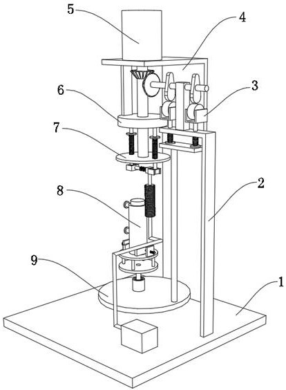
[0034] A kind of dialysis equipment for nephrology diagnosis and treatment, such as Figure 1-5As shown, it includes a base 1, a hemodialyzer 8 and a placement assembly, the top outer wall of the base 1 is fixed with a mounting frame 4 by bolts, the top outer wall of the mounting frame 4 is fixed with a servo motor 5 by bolts, and the servo motor 5 outputs The end is connected with a rotating shaft 17 through a coupling. The inner wall of the top of the mounting frame 4 is fixed with a circular sliding disc 6 by bolts. The inner wall of the circular sliding disc 6 is welded with a bump 28. The outer wall of the bottom of the rotating shaft 17 passes Bolts are fixed with a rotating plate 7, and the inner wall of the circular sliding plate 6 is rotatably connected with two I-shaped columns 24, and the outer walls of the bottom of the two I-shaped columns 24 are welded with springs 3 25, and the bottoms of the two said springs 3 25 are The outer walls are all welded with a rectan...

Embodiment 2

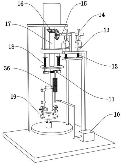
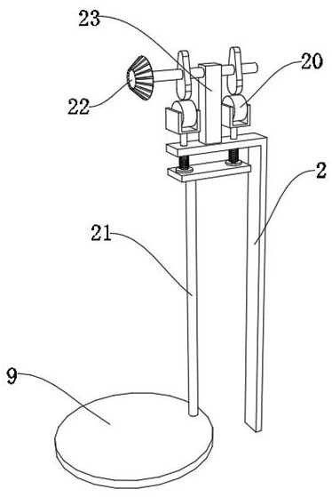
[0039] A kind of dialysis equipment for nephrology diagnosis and treatment, such as Figure 1-3 As shown, in order to improve the rate of moving up and down of the placement plate 9; the present embodiment makes the following additions on the basis of embodiment 1: the outer wall of the top of the support frame 2 is fixed with a guard plate 23 by bolts, and the inner wall of the guard plate 23 is rotatably connected There is a connecting column 15, the outer wall of the connecting column 15 is connected with a driven bevel gear 22 through a key, the outer wall of the rotating shaft 17 is connected with a driving bevel gear 16 through a key, and the outer wall of the driving bevel gear 16 is meshed with the driven bevel gear 22 outer walls, the outer wall of the connecting column 15 is fixed with a cam 14 by bolts, the outer wall of the convex column-13 top is fixed with a U-shaped frame 3 by bolts, and the inner wall of the U-shaped frame 3 is rotatably connected with a roller ...


PUM


Abstract

The invention discloses dialysis equipment for diagnosis and treatment in the nephrology department, and relates to the technical field of dialysis equipment. In order to improve the dialysis effect, the dialysis equipment comprises a base, a hemodialyzer and a placement assembly, wherein a mounting frame is arranged on the outer wall of the top of the base; a servo motor is arranged on the outerwall of the top of the mounting frame; the output end of the servo motor is connected with a rotating shaft through a coupler; a circular sliding disc is arranged on the inner wall of the top of the mounting frame; a convex block is fixed on the inner wall of the circular sliding disc; a rotating plate is arranged on the outer wall of the bottom of the rotating shaft; two I-shaped columns are movably connected to the inner wall of the circular sliding disc; springs III are fixed on the outer walls of the bottoms of the two I-shaped columns; and rectangular plates are fixed on the outer walls of the bottoms of the two springs III. According to the dialysis equipment, the hemodialyzer is arranged and can be used for carrying out dialysis treatment on a patient, the placement assembly can be used for placing and fixing the hemodialyzer, and the servo motor is arranged and can drive the rotating shaft to rotate.

Description

technical field [0001] The invention relates to the technical field of dialysis equipment, in particular to a dialysis equipment for nephrology diagnosis and treatment. Background technique [0002] The Department of Nephrology needs to use hemodialysis equipment for dialysis when treating patients, so as to treat patients. The current dialysis is set during the treatment process. In order for the dialysate to be exported in time, medical personnel need to manually shake the hemodialyzer to empty the dialysate in the hemodialyzer, thereby reducing the efficiency of dialysis. [0003] After searching, the Chinese patent application number is CN201720710223.6, which discloses a hemodialyzer, including a hemodialyzer outer shell, a hollow fiber membrane, a dialysate inlet and a blood outlet, and the upper middle of the hemodialyzer outer shell is A blood inlet is arranged at the position, a monitoring camera is arranged under the monitoring camera mounting seat, a dialysate ou...

Claims


Application Information

Patent Timeline
Patent Type & Authority Applications(China)
IPC IPC(8): A61M1/16
CPCA61M1/1621
Inventor 麦小兵王世孝
Owner 麦小兵
Why Eureka
Try Eureka