
Device for filling pipe splicing pipe with shielding gas

A technology of shielding gas and shielding gas, which is applied in the direction of hose connection devices, pipes/pipe joints/fittings, welding equipment, etc., and can solve the problems of affecting the environment and human health, labor-intensive waiting time, and large leakage loss of shielding gas. , to save time and effort for disassembly and assembly, increase operational flexibility, and compact structure

Pending Publication Date: 2021-12-14
WUXI HUAGUANG IND BOILER
View PDF0 Cites 0 Cited by
  • Summary
  • Abstract
  • Description
  • Claims
  • Application Information

AI Technical Summary

Problems solved by technology

[0004] The purpose of the present invention is to provide a protective gas filling device for splicing pipes, which can solve the problem that the protective gas needs to fill the entire pipe fitting and the leakage loss is relatively large during the gas filling process), labor-intensive (the waiting time for inflation is long when the splicing pipe fittings are long) long), environmental hazards (the protective gas filled during the filling process is directly leaked and discharged into the space environment of the working area, which affects the environment and human health, and there are health and safety hazards)

Method used


Image

  • Device for filling pipe splicing pipe with shielding gas

Examples


Embodiment Construction

[0018] It should be noted that, in the case of no conflict, the embodiments of the present invention and the features in the embodiments can be combined with each other. The present invention will be described in detail below with reference to the accompanying drawings and examples.

[0019] In order to enable those skilled in the art to better understand the solutions of the present invention, the following will clearly and completely describe the technical solutions in the embodiments of the present invention in conjunction with the accompanying drawings in the embodiments of the present invention. Obviously, the described embodiments are only Embodiments of some, but not all, embodiments of the present invention. Based on the embodiments of the present invention, all other embodiments obtained by persons of ordinary skill in the art without making creative efforts shall fall within the protection scope of the present invention.

[0020] It should be noted that the terms "f...


PUM


Abstract

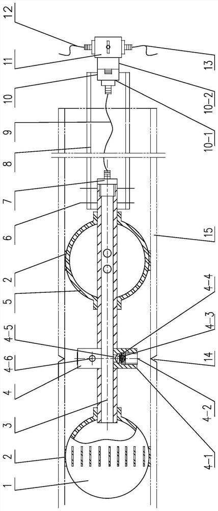
The invention relates to a device for filling a pipe splicing pipe with shielding gas. The device for filling the pipe splicing pipe comprises a gas outlet connecting pipe, the gas outlet connecting pipe is communicated with a first gas bag, a pressure check valve, a second gas bag and the first end of a three-way ball valve, the pressure check valve is located between the first gas bag and the second gas bag, and the three-way ball valve is located on the outer side of a workpiece. The second end of the three-way ball valve is communicated with a gas inlet pipe to input the shielding gas. 1, The device for filling the pipe splicing pipe is compact in structure, small in occupied space and convenient to manufacture and maintain; 2, time and labor are saved during dismounting, mounting and moving, gas loss is low, and energy conservation and environmental protection are achieved; 3, by adopting the particularity of the adjustable size of a double-gas-bag structure due to inflation expansion and deflation contraction, the device for filling the pipe splicing pipe can adapt to pipes with different specifications and irregular cavity sections; and 4, abrasion-proof heat insulation strips are arranged on the peripheries of the double gas bags, and damage and breakage caused by too high temperature of the inner wall of the contact pipe when the gas bags are abraded and expanded are effectively prevented.

Description

technical field [0001] The invention belongs to the technical field of welding tooling, and relates to a protective gas filling device for splicing pipes. Background technique [0002] As a common pressurized equipment, boilers are widely used in heating, gas supply and heating projects. Many parts of boilers, such as economizers, superheaters, water pipe systems, etc., use pipes. Because the pipes involved are of different specifications and lengths, pipe butt joints are very common in the boiler manufacturing process. [0003] Due to the advantages of good welding quality, high efficiency and easy automation, gas shielded welding has been widely used and promoted in pipe butt jointing. At present, when using gas shielded welding, when filling the pipe with shielding gas, the required shielding gas is continuously filled at both ends of the butt pipe end, so that the shielding gas in the pipe is filled to the required concentration. This method is time-consuming (it takes...

Claims


Application Information

Patent Timeline
Patent Type & Authority Applications(China)
IPC IPC(8): F16L33/00F16L37/28B23K9/16
CPCF16L33/00F16L37/28B23K9/16
Inventor 解伟解傲颀解胜飞
Owner WUXI HUAGUANG IND BOILER
Learn More