Unwinding feeding frame for glass fiber tape

A technology of glass fiber tape and feeding frame, which is applied in the direction of winding strips, sending objects, and thin material processing, etc., which can solve the problems of reduced production efficiency, low production efficiency, and high labor intensity, so as to ensure impregnated feeding and reduce friction Resistance, the effect of improving production efficiency

Pending Publication Date: 2021-12-17
盐城品冠高压电气有限公司
View PDF7 Cites 0 Cited by
  • Summary
  • Abstract
  • Description
  • Claims
  • Application Information

AI Technical Summary

Problems solved by technology

When the diameter of the epoxy pipe to be produced is relatively large, the pipe wall is relatively thick, or the axial length is relatively long, the workload of winding the glass fiber tape is huge, the labor intensity is high, and the production efficiency is low. It is also more difficult to control the uniformity of glass fiber tape winding
In addition, there are some simple devices in current production for unwinding, impregnating epoxy and feeding the glass fiber tape. It takes a long time to wind the glass fiber tape to the feeder that can be impregnated with epoxy, which further reduces the production efficiency

Method used


Image

  • Unwinding feeding frame for glass fiber tape
  • Unwinding feeding frame for glass fiber tape
  • Unwinding feeding frame for glass fiber tape

Examples


Embodiment Construction

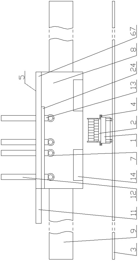
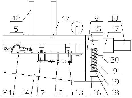
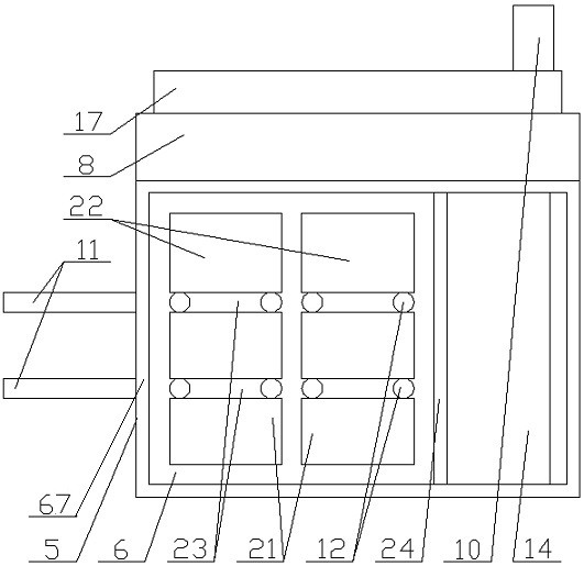
[0061] combine Figure 1~Figure 5 It can be seen that the unwinding feeding frame of the glass fiber tape includes an epoxy impregnation tank 1 that reciprocates along the track 3 through the driving device A, and the notch of the epoxy impregnation tank 1 is detachably fixedly connected with a glass fiber tape 68 The unwinding feeding frame 2 of the above-mentioned unwinding feeding frame 2 is located in the range of the epoxy impregnation tank 1, and also includes an unwinding feeding frame located above the epoxy impregnation tank 1 and reciprocatingly moving along the track beam 9 through the driving device B10 Replacement device 5, the track beam 9 is located behind the epoxy impregnation tank 1 and the unwinding feeding frame replacement device 5, and is arranged in parallel with the track 3, and the unwinding feeding frame replacement device 5 includes a horizontally arranged base frame 67, The bottom of one side of the base frame 67 is fixedly connected with the movabl...


PUM


Abstract

The invention discloses an unwinding feeding frame for a glass fiber tape. The unwinding feeding frame is detachably and fixedly connected to a notch of an epoxy impregnating tank. The unwinding feeding frame sequentially comprises an unwinding device, an impregnating conveying device, a tape scraping conveying device and a discharging conveying device along the glass fiber tape. The unwinding device, the impregnating conveying device, the tape scraping conveying device and the discharging conveying device are fixedly connected through side rods correspondingly matched with the tank walls on the two sides of the epoxy impregnating tank. A plurality of vertical rods are evenly and fixedly connected to the bottoms of the side rods. The bottoms of the outer side walls of the vertical rods are fixedly connected with flanges A. Flanges B are arranged at notches of the tank walls on the two sides of the epoxy impregnating tank. Locking devices used for locking and fixing the flanges A and the flanges B are arranged on the tank walls on the two sides of the epoxy impregnating tank. According to the structure, the unwinding feeding frame for the glass fiber tape achieves automatic unwinding, impregnating, tape scraping and gathering discharging of the glass fiber tape, and it is guaranteed that the discharged glass fiber tape can be automatically wound around an epoxy glass tube.

Description

technical field [0001] The invention relates to the technical field of drilling epoxy glass fiber tubes, in particular to an unwinding and feeding frame for glass fiber tapes. Background technique [0002] Epoxy tube (epoxy glass fiber tube) is made of electrician alkali-free glass fiber cloth soaked with epoxy resin, baked and hot-pressed in a molding mold. The cross-section is round and the rod has a high mechanical properties. Dielectric properties and good machinability. It is not only suitable for insulating structural parts in electrical equipment, but also can be used in humid environment conditions and transformer oil; it also has anti-aging, high temperature resistance, corrosion resistance and other characteristics, so it is widely used in petroleum, electric power, chemical industry, papermaking, urban Water supply and drainage, factory sewage treatment, seawater desalination, gas transmission and other industries have been widely used. [0003] In actual produ...

Claims


Application Information

Patent Timeline
Patent Type & Authority Applications(China)
IPC IPC(8): B29C70/32B29C70/54B65H19/12B65H37/02B65H23/34B65H23/26B65H23/04
CPCB29C70/32B29C70/54B65H19/12B65H37/02B65H23/34B65H23/26B65H23/04
Inventor 卫爱京葛超
Owner 盐城品冠高压电气有限公司
Why Eureka
Try Eureka