
Automobile exhaust pipe heat insulation system and automobile with same

A technology for automobile exhaust and heat insulation parts, which is applied in the direction of exhaust devices, vehicle parts, noise reduction devices, etc., and can solve the problem that the waste heat utilization device and the heat shield cannot be in the same position, the heat shield cannot be moved and disassembled, and the pipeline is complicated and other problems, to achieve the effect of simple structure, convenient disassembly, and improved heat utilization

Active Publication Date: 2021-12-17
GUANGZHOU AUTOMOBILE GROUP CO LTD
View PDF6 Cites 0 Cited by
  • Summary
  • Abstract
  • Description
  • Claims
  • Application Information

AI Technical Summary

Problems solved by technology

At present, in order to reduce the heat of the exhaust pipe, most heat shields are installed on the exhaust pipe, but the heat shield cannot be moved and is inconvenient to disassemble, or a waste heat utilization device is added, as shown in CN201507346U, but the waste heat utilization device and the heat shield It cannot be at the same location, and the waste heat utilization device has many parts and complicated pipelines

Method used


Image

  • Automobile exhaust pipe heat insulation system and automobile with same
  • Automobile exhaust pipe heat insulation system and automobile with same

Examples


Embodiment Construction

[0035] For better understanding and implementation, the technical solutions in the embodiments of the present invention will be clearly and completely described below in conjunction with the drawings in the embodiments of the present invention.

[0036] In the description of the present invention, it should be noted that if the terms "upper", "lower", "front", "rear", "left", "right", "vertical", "horizontal", "top ", "bottom", "inner", "outer", etc., the orientation or positional relationship indicated by these terms is based on the orientation or positional relationship shown in the drawings, and is only for the convenience of describing the present invention and simplifying the description, rather than indicating or It should not be construed as limiting the invention by implying that a referenced device or element must have a particular orientation, be constructed, and operate in a particular orientation.

[0037] Unless otherwise defined, all technical and scientific term...


PUM


Abstract

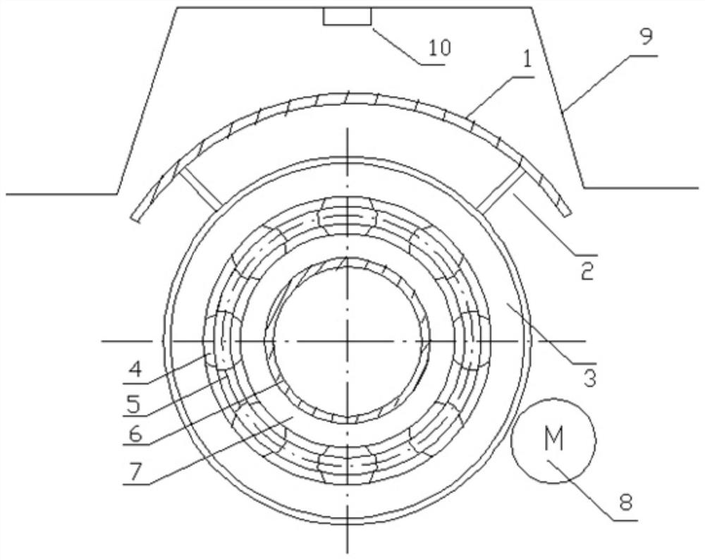
The invention provides an automobile exhaust pipe heat insulation system and an automobile with the same. The automobile exhaust pipe heat insulation system comprises a heat insulation piece, a rotating piece and a driving piece which are arranged in sequence. The heat insulation piece is fixedly connected with the rotating piece; and the rotating piece can rotate under the driving of the driving piece, so that the heat insulation piece rotates relative to the automobile exhaust pipe. The automobile exhaust pipe heat insulation system provided by the invention is simple in structure, the position of the heat insulation piece can be adjusted according to different heat released by an exhaust pipe, so that high-temperature heat insulation can be achieved, and waste heat utilization at low temperature can also be achieved.

Description

technical field [0001] The invention relates to the technical field of automobile tail gas utilization, in particular to an automobile exhaust pipe heat insulation system and an automobile having the same. Background technique [0002] After the engine burns fuel, about 40% of the energy is dissipated in the form of exhaust waste heat, and the temperature of the exhaust pipe of a car can reach 400-500°C. Especially after the implementation of the National VI emission standards, turbocharging technology and particulate filters are widely used in automobiles, which makes the temperature of automobile exhaust higher. Turbocharging is a technology that uses the exhaust gas generated by the operation of the internal combustion engine to drive the air compressor, which can significantly increase the intake air volume of the engine, thereby improving the power and fuel economy of the engine. The ceramic filter in the system can effectively reduce the emission of particulate matter...

Claims


Application Information

Patent Timeline
Patent Type & Authority Applications(China)
IPC IPC(8): F01N13/08F01N13/14F01N13/18B60R13/08
CPCF01N13/08F01N13/14F01N13/1822B60R13/0876Y02T10/12
Inventor 段炼黎帅袁侠义葛吉伟林铁平张傲同
Owner GUANGZHOU AUTOMOBILE GROUP CO LTD
Learn More