
Auxiliary control system based on industrial electric furnace

An auxiliary control system, electric furnace technology, applied in furnace control devices, furnaces, furnace components, etc., can solve major fire safety accidents, uncontrollable electric furnace temperature, temperature rise and other problems, and achieve the effect of preventing major safety accidents.

Pending Publication Date: 2021-12-17
襄阳尚能电气有限公司
View PDF0 Cites 0 Cited by
  • Summary
  • Abstract
  • Description
  • Claims
  • Application Information

AI Technical Summary

Problems solved by technology

[0005] The purpose of the present invention is to solve the problem that the internal temperature of the electric furnace in the prior art will rise sharply when it is in use, and the workpiece will be heated and melted. If the aging temperature control equipment of the electric furnace fails, the temperature of the electric furnace cannot be controlled, resulting in the failure of the electric furnace Fires are caused by high temperatures. The existing technology cannot accurately detect and extinguish the large fires when a fire occurs, resulting in major fire safety accidents. The proposed auxiliary control system based on industrial electric furnaces

Method used


Image

  • Auxiliary control system based on industrial electric furnace
  • Auxiliary control system based on industrial electric furnace
  • Auxiliary control system based on industrial electric furnace

Examples


Embodiment Construction

[0025] The following will clearly and completely describe the technical solutions in the embodiments of the present invention with reference to the accompanying drawings in the embodiments of the present invention. Obviously, the described embodiments are only some, not all, embodiments of the present invention.

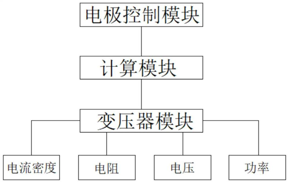
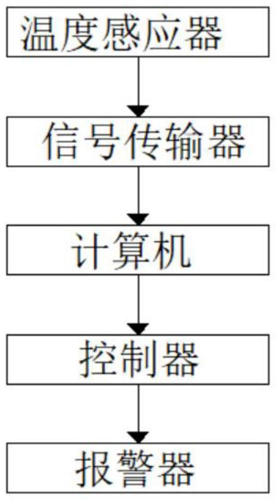
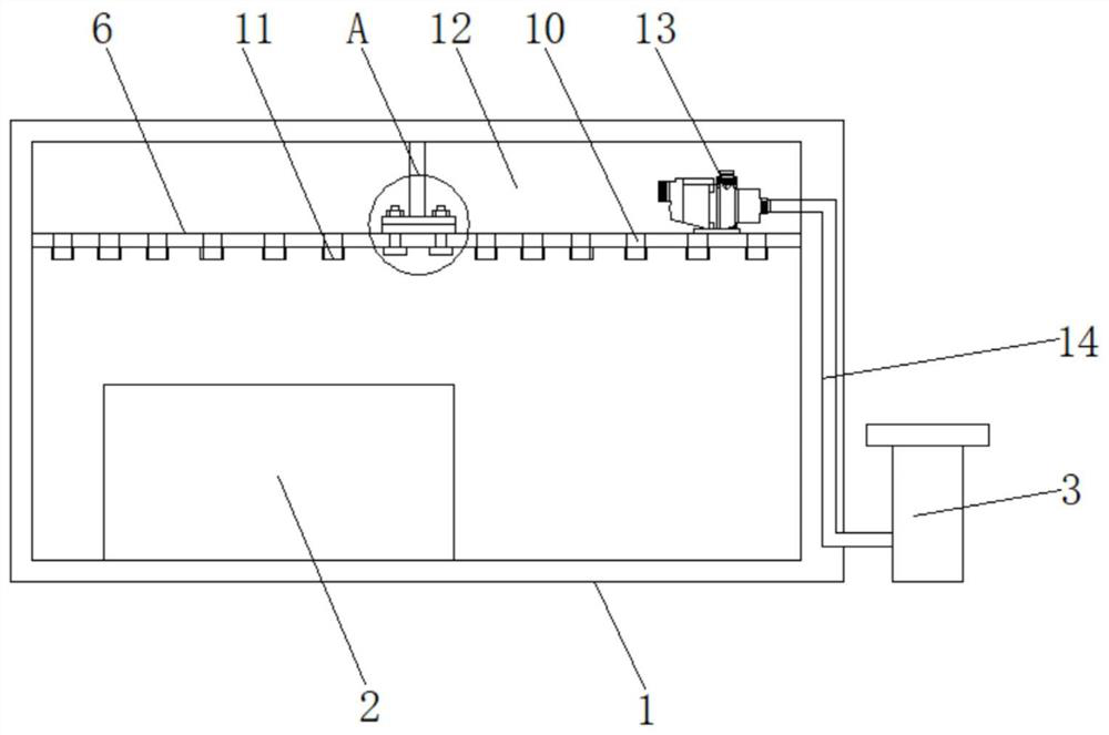
[0026] refer to Figure 1-4 , an auxiliary control system based on industrial electric furnaces, including a furnace room 1, characterized in that: an electric furnace 2 is provided inside the furnace room 1, a fire hydrant 3 is provided on one side of the furnace room 1, and a fire hydrant 3 is provided at the top of the furnace room 1. There is a support column 4, the bottom of the support column 4 is fixedly connected with a first flange 5, the top of the furnace room 1 is located at the bottom of the support column 4, and a fireproof roof 6 is provided, and the middle position of the top of the fireproof roof 6 is fixedly connected with a second flange. The blue ...


PUM


Abstract

The invention relates to the technical field of industrial electric furnaces, in particular to an auxiliary control system based on an industrial electric furnace, the auxiliary control system comprises a furnace room and is characterized in that the electric furnace is arranged in the furnace room, a fire hydrant is arranged on one side of the furnace room, and a supporting column is arranged in the middle of the top of the furnace room; a first flange plate is fixedly connected to the bottom of the supporting column, and a fireproof roof is arranged at the position, located at the bottom of the supporting column, of the top of the furnace room; the auxiliary control system has the beneficial effects that through the arrangement of a temperature sensor, a signal transmitter, a computer, a controller and an alarm, the temperature sensor senses the temperature generated by the electric furnace; and received temperature information is transmitted to the computer through the signal transmitter, a computer system compares the received temperature information with the temperature information of a safety value, and when the received information is higher than the temperature safety value information, the controller controls the alarm to sound and give out alarm sound, and a worker can be reminded of reducing the temperature in the electric furnace.

Description

technical field [0001] The invention relates to the technical field of industrial electric furnaces, in particular to an auxiliary control system based on industrial electric furnaces. Background technique [0002] Industrial furnaces are divided into two types according to the heating method: one is flame furnace (or fuel furnace), which uses the combustion heat of solid, liquid or gas fuel in the furnace to heat the workpiece, and the second type is electric furnace, which can be divided into It is a resistance furnace, induction furnace, electric arc furnace, plasma furnace, electron beam furnace, etc. Compared with a fuel furnace, the advantages of an electric furnace are: the atmosphere in the furnace is easy to control; the material is heated quickly; the heating temperature is high; the temperature is easy to control; the production process is easier. Realize mechanization and automation; good labor hygiene conditions; high thermal efficiency; good product quality, an...

Claims


Application Information

Patent Timeline
IPC IPC(8): F27D19/00F27D21/00A62C31/05A62C31/28A62C37/40
CPCF27D19/00F27D21/0014A62C31/05A62C31/28A62C37/40F27D2021/0057
Inventor 董磊磊王文杰
Owner 襄阳尚能电气有限公司
Learn More