Light sensing array module and light transmitting and receiving device

An array module and optical sensing technology, applied in radiation control devices, semiconductor devices, electrical components, etc., can solve the problem of edge noise increase

Pending Publication Date: 2021-12-17
EGIS TECH
View PDF0 Cites 0 Cited by
  • Summary
  • Abstract
  • Description
  • Claims
  • Application Information

AI Technical Summary

Problems solved by technology

However, when the assembly position of the light sensing array in the housing deviates, it is easy to cause part of the field of view to be blocked by the housing, resulting in increased edge noise
[0005] If an angular filter is used to filter out the large-angle light outside the signal, although the signal-to-noise ratio is improved, the quantum efficiency is sacrificed.

Method used


Image

  • Light sensing array module and light transmitting and receiving device
  • Light sensing array module and light transmitting and receiving device
  • Light sensing array module and light transmitting and receiving device

Examples


Embodiment Construction

[0017] Reference will now be made in detail to the exemplary embodiments of the present invention, examples of which are illustrated in the accompanying drawings. Wherever possible, the same reference numbers are used in the drawings and descriptions to refer to the same or like parts.

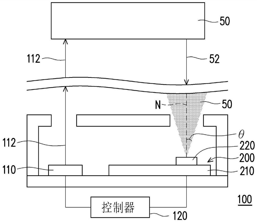
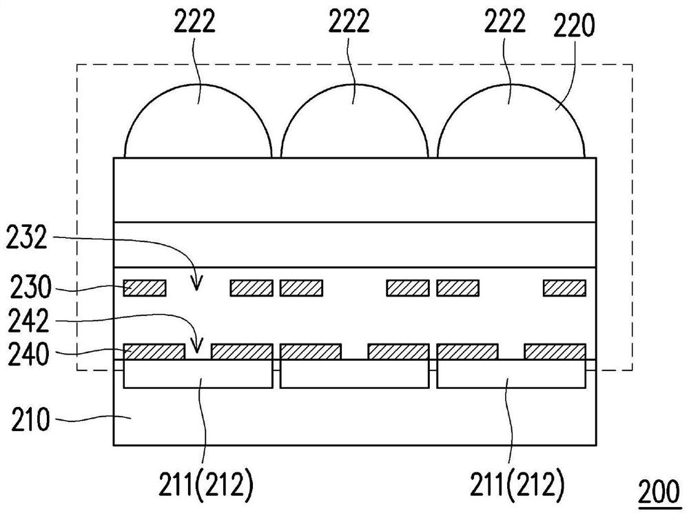
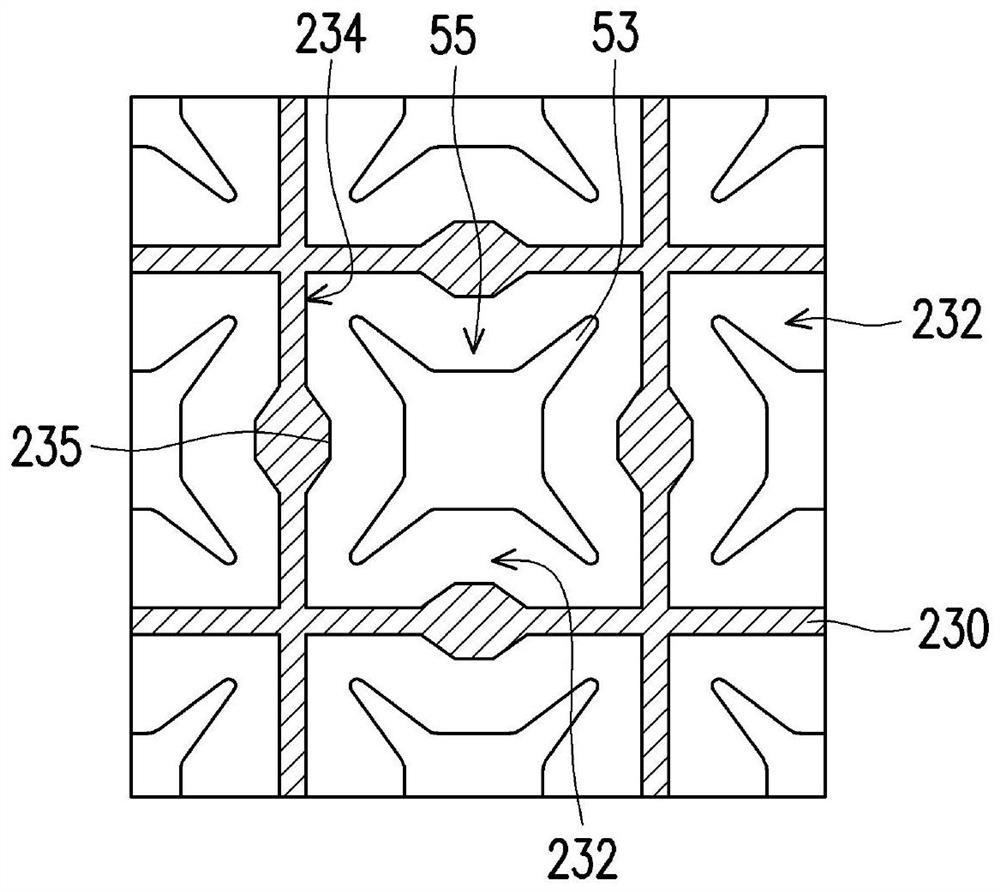
[0018] figure 1 is a schematic cross-sectional view of an optical transceiver device according to an embodiment of the present invention, figure 2 for figure 1 The cross-sectional schematic diagram of the photo-sensing array module in , while image 3 for figure 2 A schematic diagram of the top view of the shading layer and the light spot in . Please refer to Figure 1 to Figure 3 , the optical transceiver device 100 of this embodiment includes a light emitting element 110 and a light sensing array module 200 . The light emitting element 110 is used for emitting a light beam 112 . The light sensing array module 200 is used for sensing the light 52 generated by the object 50 after refl...


PUM


Abstract

The invention provides a light sensing array module and a light transmitting and receiving device. The light sensing array module comprises a light sensing array substrate, a lens array and a light shielding layer. The light sensing array substrate includes a plurality of pixels arranged in an array. The lens array is arranged above the light sensing array substrate and comprises a plurality of micro lenses which are respectively arranged above the pixels. The light shielding layer is arranged between the light sensing array substrate and the lens array and comprises a plurality of light passing openings. The light-passing openings are respectively arranged between the micro-lenses and the pixels, and light of which the incident angle of the incident lens array is at least within 14 degrees can be transmitted to the pixels through the light-passing openings and cannot be shielded by the light shielding layer.

Description

technical field [0001] The present invention relates to an optical module and device, and in particular to an optical sensing array module and an optical transceiver device. Background technique [0002] With the advancement of optoelectronic technology, a time-of-flight ranging device or LiDAR has been developed, which can measure the time of flight of light to calculate the distance of an object. [0003] A time-of-flight ranging device, or lidar, consists of a laser emitter and a light-sensing array. The laser emitter emits laser light to irradiate external objects. External objects then reflect the laser light back to the photo-sensing array. [0004] In the conventional time-of-flight distance measuring device or lidar, the opening position and size of the casing determine the field of view angle of the light detected by the photo-sensing array. However, when the assembly position of the light sensing array in the housing deviates, part of the field of view is easily...

Claims


Application Information

Patent Timeline
Patent Type & Authority Applications(China)
IPC IPC(8): H01L27/146
CPCH01L27/14621H01L27/14627H01L27/1463H01L27/14634
Inventor 范辰玮
Owner EGIS TECH
Why Eureka
Try Eureka