Outdoor integrated cabinet for optical relay station of optical fiber transmission system

A technology of optical fiber transmission and relay stations, which is applied in the direction of electrical equipment shells/cabinets/drawers, optics, light guides, etc., which can solve the problems that the cabinets cannot operate around the clock, the failure rate of air conditioners that are easy to be blocked, and the heat dissipation environment of air conditioners is poor, so as to save space in the cabinet , Improve power consumption utilization, reduce the effect of opening the door

Pending Publication Date: 2021-12-17
JIANGSU HENGTONG PHOTOELECTRIC +1
View PDF15 Cites 0 Cited by
  • Summary
  • Abstract
  • Description
  • Claims
  • Application Information

AI Technical Summary

Problems solved by technology

[0006] For this reason, the technical problem to be solved by the present invention is to overcome the problem that the interior of the outdoor cabinet is occupied by equipment in the prior art. During the operation of the equipment, the cabinet door needs to be opened, and the personnel stand outside the cabinet to operate, which makes the cabinet unable to work around the clock, and the cabinet uses The air conditioning system is integrated on the cabinet door, or installed inside the card slot on the side of the cabinet, resulting in poor cooling environment of the air conditioner, easy blockage and high failure rate of the air conditioner

Method used


Image

  • Outdoor integrated cabinet for optical relay station of optical fiber transmission system
  • Outdoor integrated cabinet for optical relay station of optical fiber transmission system
  • Outdoor integrated cabinet for optical relay station of optical fiber transmission system

Examples


Embodiment Construction

[0026] The present invention will be further described below in conjunction with the accompanying drawings and specific embodiments, so that those skilled in the art can better understand the present invention and implement it, but the examples given are not intended to limit the present invention.

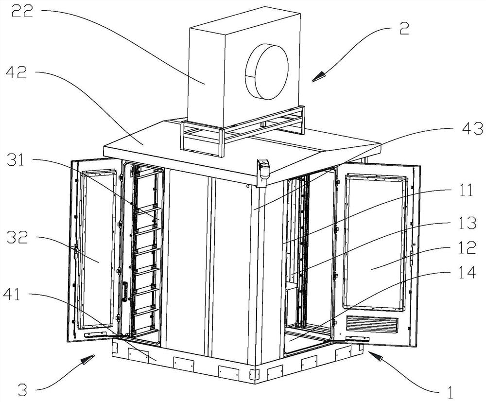
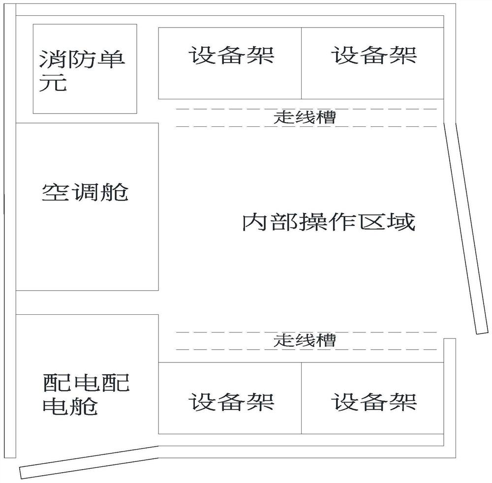
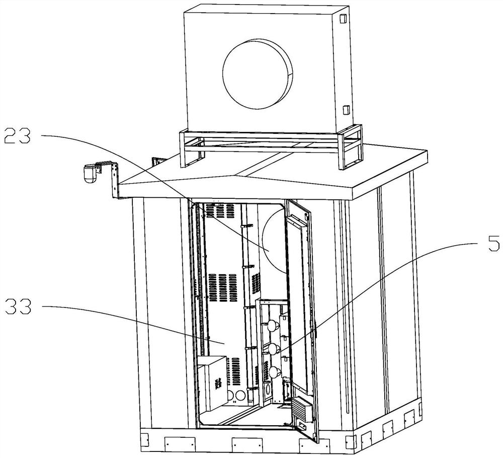
[0027] refer to Figure 1 to Figure 5 As shown, the outdoor integrated cabinet of the optical relay station of the optical fiber transmission system of the present invention includes an equipment installation unit 1, an air conditioning unit 2, and a power distribution unit 3. The equipment installation unit 1 includes an equipment installation cabin 11 located inside the integrated cabinet and for Enter the equipment cabin door 12 of the equipment installation cabin 11; the air-conditioning unit 2 includes an air-conditioning cabin 21 located inside the integrated cabinet, an air-conditioning external unit 22 located on the outer top of the integrated cabinet, and a power environm...


PUM


Abstract

The invention relates to an outdoor integrated cabinet for an optical relay station of an optical fiber transmission system. The integrated cabinet comprises an equipment installation unit, an air conditioning unit and a power distribution unit. The equipment installation unit comprises an equipment installation cabin arranged in the integrated cabinet and an equipment cabin door used for entering the equipment installation cabin. The air conditioning unit comprises an air conditioning cabin, an air conditioning external unit, a power environment monitoring module and an air conditioning internal unit which are arranged in the integrated cabinet; and the power distribution unit comprises a comprehensive power distribution cabin, a monitoring module, a power supply module and a comprehensive cabin door which are arranged in the integrated cabinet, the power supply module is connected with equipment in the equipment installation unit, the power environment monitoring module, the air conditioner indoor unit and the air conditioner outdoor unit, and the comprehensive power distribution cabin and the equipment installation cabin are separated from each other. The integrated cabinet is compact in layout and high in integration, adopts an internal operation mode, separates the equipment installation cabin from the comprehensive power distribution cabin, can save the space in the cabinet body, and improves the power consumption utilization rate of the air conditioner based on the composite function of the heat pipe through the arrangement of the heat pipe air conditioner and the height difference between the air conditioner outdoor unit and the air conditioner indoor unit.

Description

technical field [0001] The invention relates to the technical field of optical fiber transmission, in particular to an outdoor integrated cabinet of an optical relay station of an optical fiber transmission system. Background technique [0002] In the optical fiber transmission system, the optical relay station plays the role of signal amplification and channel equalization. The traditional optical relay station is set up in a civil engineering room with a construction area of ​​more than 60 square meters. Due to the large area of ​​the equipment room and the need to consider the requirements for the entry and exit of optical cables, it is difficult to select a site for the equipment room, resulting in uneven lengths of optical transmission sections and optical relay distances. Compared with the theoretical model, the deviation is large, which seriously affects the transmission performance, leads to a serious shortening of the non-electric relay distance, and greatly increas...

Claims


Application Information

Patent Timeline
Patent Type & Authority Applications(China)
IPC IPC(8): H05K5/02H05K7/20G02B6/44
CPCH05K5/0217H05K7/20209G02B6/4452
Inventor 张小倩焦明涛郭靖萱张曜晖郝祥勇赵璋卓董海涛陈文雄吴敏黄劲松
Owner JIANGSU HENGTONG PHOTOELECTRIC
Why Eureka
Try Eureka