Small-size lens product multi-line cutting fixing device, cutting system and cutting method

A multi-wire cutting and fixing device technology, applied in the field of optical parts processing, can solve the problems of reduced product utilization, low cutting yield, and high cutting difficulty, so as to improve utilization and yield, improve cutting accuracy, and increase the number of cuts Effect

Active Publication Date: 2021-12-21
FOCTEK PHOTONICS LNC
View PDF9 Cites 1 Cited by
  • Summary
  • Abstract
  • Description
  • Claims
  • Application Information

AI Technical Summary

Problems solved by technology

[0003] In the field of optical parts processing, multi-wire cutting equipment is currently mainly used for cutting large raw material blank parts. If the semi-finished products that have been polished or coated are cut, on the one hand, due to the large damage to the finish during the cutting process, cutting The difficulty is high, resulting in a low cutting yield of products with high requirements on smoothness and coating appearance
On the other hand, since the current multi-wire cutting tooling for raw material blank parts is generally a stainless steel plate, the blank product is bonded to the plate for wire cutting. In order to prevent the diamond wire from directly cutting the stainless steel plate and causing failures such as wire breakage, precise control of cutting is required It is not possible to completely cut through the bottom of the tooling, and a certain distance needs to be reserved, which makes it impossible to completely cut through the product and reduces the utilization rate of the product

Method used


Image

  • Small-size lens product multi-line cutting fixing device, cutting system and cutting method
  • Small-size lens product multi-line cutting fixing device, cutting system and cutting method
  • Small-size lens product multi-line cutting fixing device, cutting system and cutting method

Examples


Embodiment Construction

[0031] The following will clearly and completely describe the technical solutions in the embodiments of the present invention with reference to the accompanying drawings in the embodiments of the present invention. Obviously, the described embodiments are only some, not all, embodiments of the present invention. Based on the embodiments of the present invention, all other embodiments obtained by persons of ordinary skill in the art without creative efforts fall within the protection scope of the present invention.

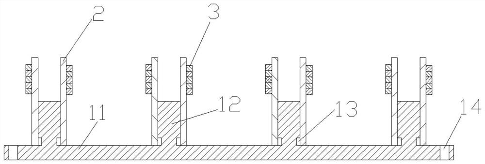
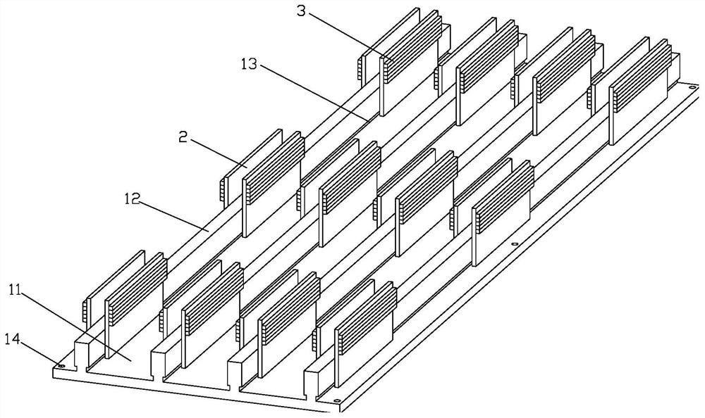
[0032] Such as figure 1 As shown, it is a schematic diagram of the multi-wire cutting and fixing device for small-sized lens products of the present invention, including a tooling plate (1) used to connect with the lifting platform of the multi-wire cutting machine and a plurality of tooling plates (1) installed on the tooling plate (1) for Fix the leaning body (2) of the strip-shaped product (3) to be cut; specifically, the material of the tooling plate (1) is sta...


PUM


Abstract

The invention relates to the technical field of optical part machining, in particular to a small-size lens product multi-line cutting fixing device, a cutting system and a cutting method. The cutting fixing device comprises a tool plate connected with a multi-wire cutting machine and leaning bodies used for fixing strip-shaped products to be cut; the tool plate comprises a bottom plate and stand columns fixedly arranged on the same side plate face of the bottom plate at intervals; the surface of one side of each leaning body is fixedly connected with the side wall of one transverse side of each stand column, the surfaces of the other sides of the leaning bodies are used for fixing the to-be-cut products, the bottom edge of each leaning body is parallel to and fixedly connected with the plate face of the bottom plate, and the top edge of each leaning body is higher than the top edge of each stand column; and the fixed connection positions of the to-be-cut products and the leaning bodies are located between the top edges of the leaning bodies and the top edges of the stand columns. According to the small-size lens product multi-wire cutting fixing device and the cutting method, multi-wire cutting can be carried out on small-size semi-finished products which are high in smoothness requirement and have coating appearance, and the product utilization rate and the yield are improved.

Description

technical field [0001] The application relates to the technical field of optical parts processing, in particular to a multi-wire cutting and fixing device for small-sized lens products, a cutting system and a cutting method. Background technique [0002] Multi-wire cutting is a high-speed reciprocating motion of a plurality of diamond wires that are parallel to each other and arranged at intervals in sequence, and cuts the raw material to be cut that moves closer to the diamond wire. Brittle materials are cut into hundreds of thin slices at once. Due to its advantages of high precision, high speed and low loss, CNC multi-wire cutting machine has been widely used in the field of high-end manufacturing technology. [0003] In the field of optical parts processing, multi-wire cutting equipment is currently mainly used for cutting large raw material blank parts. If the semi-finished products that have been polished or coated are cut, on the one hand, due to the large damage to ...

Claims


Application Information

Patent Timeline
Patent Type & Authority Applications(China)
IPC IPC(8): B24B27/06B24B41/06B24B55/02B28D1/06B28D5/04B28D7/00B28D7/02B28D7/04
CPCB24B27/0633B24B27/0675B24B41/06B24B55/02B28D1/06B28D7/04B28D7/00B28D5/045B28D5/0058B28D5/0082B28D7/02B28D5/0076Y02P40/57
Inventor 朱建龙魏德全肖亮祖李健蒋传淋
Owner FOCTEK PHOTONICS LNC
Why Eureka
Try Eureka