
Multi-stage cooling and purifying device for cracked oil gas

A purification device, oil and gas technology, applied in the field of waste cracking, can solve the problems of oil quality decline, different oil and gas components, complex components, etc., to achieve comprehensive utilization, improve cracking efficiency, and realize the effect of waste heat.

Active Publication Date: 2021-12-24
NIUTECH ENVIRONMENT TECHNOLOGY CORPORATION
View PDF7 Cites 0 Cited by
  • Summary
  • Abstract
  • Description
  • Claims
  • Application Information

AI Technical Summary

Problems solved by technology

[0002] At present, waste rubber and waste plastics can be processed by pyrolysis. These polymer materials can produce a large amount of recyclable oil and gas after pyrolysis. However, the composition of this part of oil and gas is relatively complicated, and it is difficult to reasonably process this part of oil and gas with existing technologies. recovery and utilization, and the components of oil and gas from different sources are different, how to separate this part of oil and gas well, separate as much oil as possible, and improve the recovery rate of oil is difficult in the existing technology solved problem;
[0003] At the same time, due to the difference in cracking temperature, the oil and gas obtained by cracking also contain certain substances that can be cracked again. This part of the oily substance cannot be effectively recycled, and it will increase the burden on the subsequent oil treatment section after being directly discharged as oil. , the quality of the obtained oil product decreases, and at the same time, the yield of the cracked product is reduced; the inventor's prior application CN201821301314.5 discloses a kind of oil separation and cooling device for cracked oil products, which uses the middle part of the oil and gas condensation tower A to directly feed The way of cracking oil and gas to condense the intake air also cannot collect and process the above-mentioned substances that can be cracked twice. Therefore, how to better solve the above problems has become one of the technical problems that the inventors have to work hard to solve

Method used


Image

  • Multi-stage cooling and purifying device for cracked oil gas
  • Multi-stage cooling and purifying device for cracked oil gas
  • Multi-stage cooling and purifying device for cracked oil gas

Examples


Embodiment 1

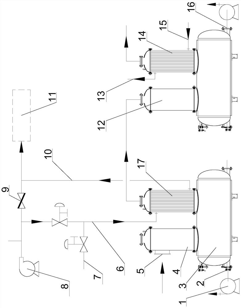
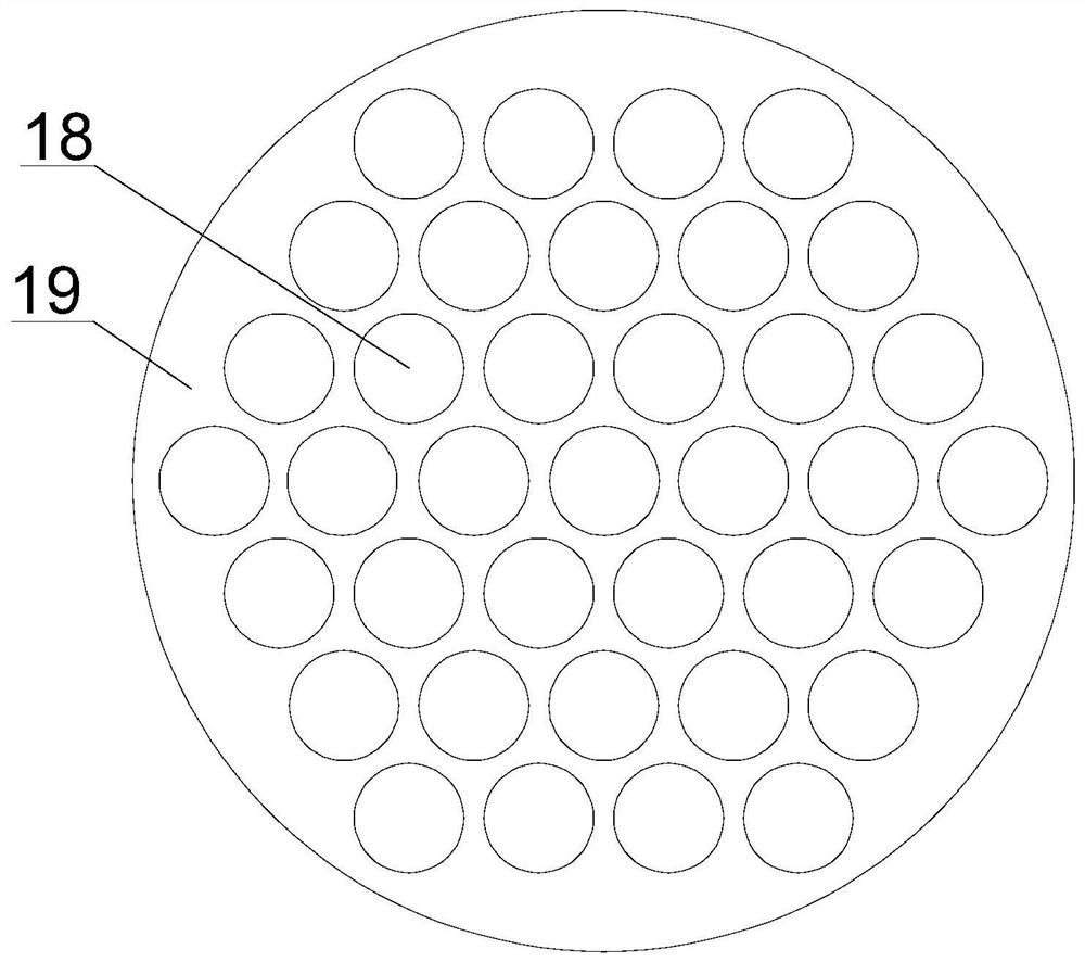
[0022] Such as figure 1 and 3 As shown, a multi-stage cooling and purification device for cracking oil and gas, the device includes a first cooler and a second cooler arranged in series. The two coolers have the same structure, and both include horizontally arranged oil storage tanks. There are oil-gas inlet tower and oil-gas condensing tower. The oil-gas condensing tower is provided with a condensing pipeline 18, and a cooling cavity 19 is set outside the condensing pipeline 18. The cooling cavity is connected with a cooling medium inlet and a cooling medium outlet, and the oil and gas enter the oil-gas condensing tower. Then move upward along the condensing pipeline;

[0023] Wherein the side of the first oil-gas inlet tower 4 is provided with a first oil-gas inlet 5, and a flue gas circulation device is connected to the first oil-gas condensation tower 17; the flue gas circulation device includes a flue gas inlet pipe 6 and a flue gas return pipe 10, and The gas inlet pip...

Embodiment 2

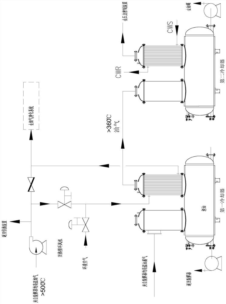
[0027] The process of using the multi-stage cooling and purification device for cracking oil and gas described in Example 1 to carry out the cooling and purification of oil and gas, the specific process is as follows:

[0028]The high-temperature oil vapor from the cracker enters the first oil and gas inlet tower through the first oil and gas inlet, and fills the tower body, and finally presses down into the first oil storage tank to contact with the pre-installed oil in the oil storage tank, and elute through it For the solid components, since the oil in the oil storage tank is not fully loaded, there is a cavity at the top of the first oil storage tank to facilitate the movement of oil and gas, and the oil and gas after preliminary elution enter the first oil and gas condensation tower;

[0029] At this time, the high-temperature flue gas, which is the heat source of the cracker, enters the flue gas inlet pipe through the heat recovery circulating fan, and at the same time, b...

Embodiment 3

[0032] The process of using the multi-stage cooling and purification device for cracking oil and gas described in Example 1 to carry out the cooling and purification of oil and gas, the specific process is as follows:

[0033] like figure 2 As shown, the high-temperature oil vapor from the cracker enters the first oil-gas inlet tower through the first oil-gas inlet, fills the tower body, and finally presses down into the first oil storage tank to contact with the pre-installed oil in the oil storage tank. It elutes the solid components in it. Since the oil in the oil storage tank is not fully loaded, there is a cavity on the top of the first oil storage tank to facilitate the movement of oil and gas. After the initial elution, the oil and gas enter the first oil and gas condensation tower;

[0034] At this time, the high-temperature flue gas, which is the heat source of the cracker, enters the flue gas inlet pipe through the heat recovery circulating fan, and at the same tim...


PUM


Abstract

The invention belongs to the technical field of waste cracking, and particularly relates to a multi-stage cooling and purifying device for cracked oil gas, wherein the device comprises a first cooler and a second cooler which are connected in series, the two coolers are the same in structure and each comprise a horizontally-arranged oil storage tank, and the oil storage tanks are connected with an oil gas inlet tower and an oil gas condensing tower, wherein an oil gas inlet is formed in the side surface of the first oil gas inlet tower, and the first oil gas condensing tower is connected with a flue gas circulating device; an oil gas inlet is formed in the top of the second oil gas inlet tower, and the first oil gas condensing tower is connected with a cooling water circulating device; and a bottom oil outlet of a first oil storage tank is connected with an inlet of a cracker through a circulating pump. According to the multi-stage cooling and purifying device for the cracked oil gas with the structure, residual oil enriched at the bottom can be sent back to the cracker through the first cooler for secondary cracking, the cracking efficiency is improved, meanwhile, the purity of the cracked gas is improved through multi-stage cooling, and comprehensive utilization of waste heat is achieved.

Description

technical field [0001] The invention belongs to the technical field of waste cracking, in particular to a multi-stage cooling and purification device for cracking oil and gas. Background technique [0002] At present, waste rubber and waste plastics can be processed by pyrolysis. These polymer materials can produce a large amount of recyclable oil and gas after pyrolysis. However, the composition of this part of oil and gas is relatively complicated, and it is difficult to reasonably process this part of oil and gas with existing technologies. recovery and utilization, and the components of oil and gas from different sources are different, how to separate this part of oil and gas well, separate as much oil as possible, and improve the recovery rate of oil is difficult in the existing technology solved problem; [0003] At the same time, due to the difference in cracking temperature, the oil and gas obtained by cracking also contain certain substances that can be cracked aga...

Claims


Application Information

Patent Timeline
IPC IPC(8): B01D5/00C10B53/07
CPCB01D5/0012C10B53/07Y02P20/129
Inventor 赵凤娇刘萍张广震吴元旭王大龙牛斌
Owner NIUTECH ENVIRONMENT TECHNOLOGY CORPORATION
Features
  • Generate Ideas
  • Intellectual Property
  • Life Sciences
  • Materials
  • Tech Scout
  • Unparalleled Data Quality
  • Higher Quality Content
  • 60% Fewer Hallucinations
Learn More