Structured light hand-eye calibration method based on coordinate system servo alignment

A technology of hand-eye calibration and structured light, which is applied in the field of computer vision, can solve the problems that the calibration accuracy depends on the professional level of the operator, the result consistency is poor, and the accuracy is insufficient, so as to achieve a high degree of automation, good consistency, and reduce the dependence on the technical level. Effect

Pending Publication Date: 2021-12-24
SHENYANG INST OF AUTOMATION - CHINESE ACAD OF SCI
View PDF0 Cites 0 Cited by
  • Summary
  • Abstract
  • Description
  • Claims
  • Application Information

AI Technical Summary

Problems solved by technology

The traditional 3D hand-eye calibration method often uses a robot to drive the camera to move, collect images under multiple poses on the calibration board, obtain enough calibration data, and then complete the hand-eye calibration through matrix fitting, pose decomposition and other steps; this method has many disadvantages: (1) The attitude decomposition process often faces the problem of insufficient accuracy; (2) When there is a slight disturbance in the system, the result consistency of the fitted matrix after attitude decomposition is poor; (3) During the calibration process, the choice of the robot’s photographing attitude It plays a vital role in the calibration results, and the calibration accuracy is overly dependent on the professional level of the operator;

Method used


Image

  • Structured light hand-eye calibration method based on coordinate system servo alignment
  • Structured light hand-eye calibration method based on coordinate system servo alignment
  • Structured light hand-eye calibration method based on coordinate system servo alignment

Examples


Embodiment Construction

[0051] The invention will be further described in detail below with reference to the accompanying drawings and examples.

[0052] Establish design and user coordinate system 1. The calibration block

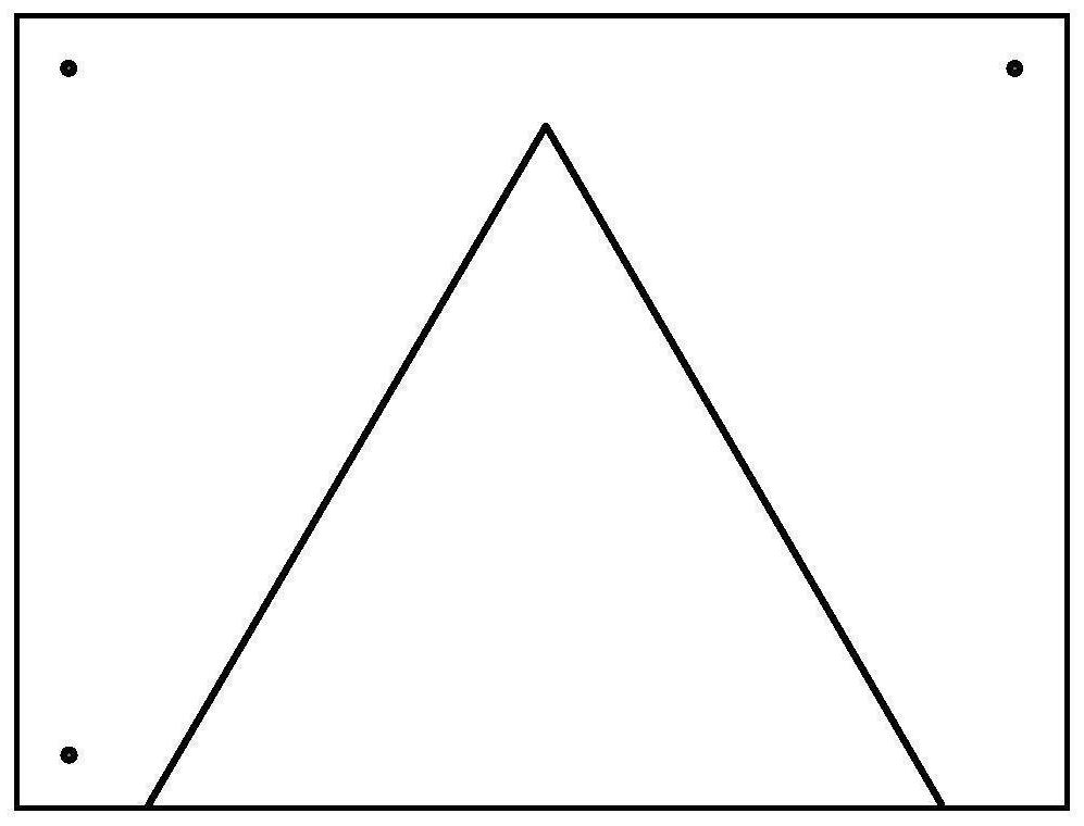
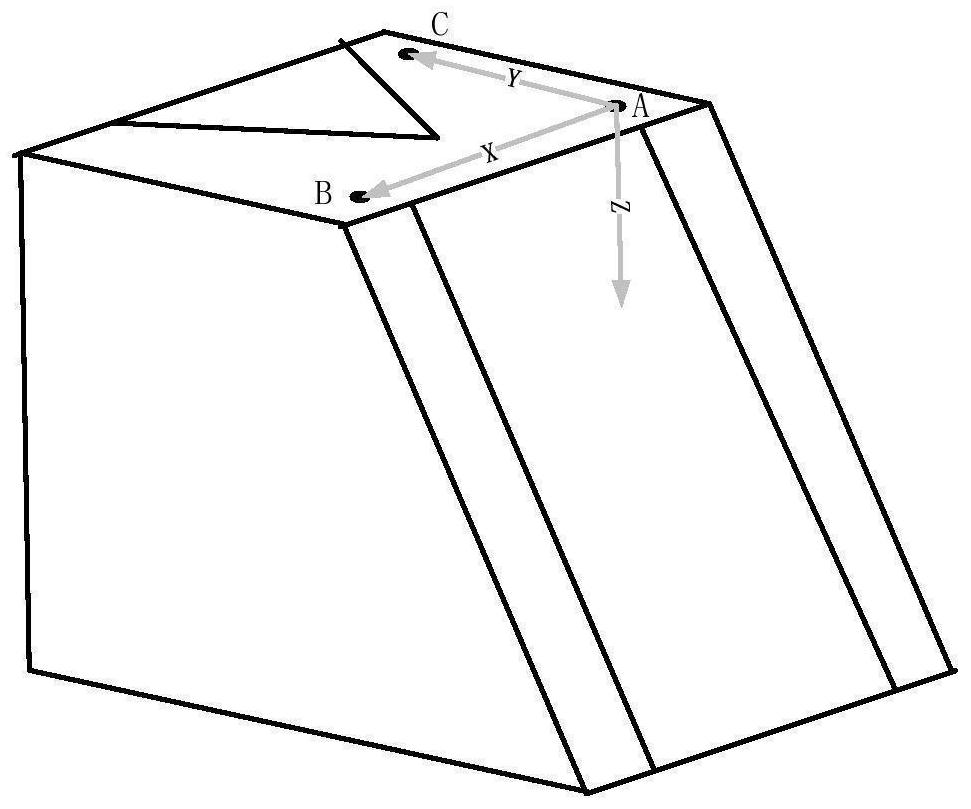
[0053] Light applied to the robot structure and a three-dimensional hand-eye camera calibration method, using a calibrated geometrical information block of specially designed, highly accurately estimate a three-dimensional structure of the light relative pose of the camera coordinate system; calibration block mainly comprising a special design on the surface and the ramp surface, the surface having three circular holes and grooves of an isosceles triangle, with a ramp surface on which the parallel groove; figure 1 Shows a schematic view of the surface of the calibration block, three circular holes is used to establish the robot coordinate system user (user coordinate system calibration block), is also used to estimate the relative attitude offline rx, rz, isosceles triangle recess fo...


PUM


Abstract

The invention relates to the field of three-dimensional hand-eye calibration, and aims at three-dimensional calibration of a structured light camera coordinate system and a robot tail end coordinate system. A structured light sensor is installed at the tail end of a robot, and the three-dimensional relative pose relation of a structured light camera coordinate system is estimated with high precision through an off-line and on-line two-step estimation method by means of geometric information of a specially-designed calibration block. The method specifically comprises the steps that by means of special geometric information of the calibration block, an operator can manually adjust the posture of the tail end of a robot, a camera is driven to move to collect images, and the initial relative pose of the structured light camera coordinate system is rapidly obtained; and after the initial relative pose is obtained, the robot can drive the camera to collect images through automatic operation including a specified path, the relative pose of the structured light camera coordinate system is estimated in an algorithm loop iteration mode, and finally a high-precision calibration result is obtained. The method has high practicability in robot hand-eye vision application based on structured light, such as welding seam tracking and robot automatic polishing.

Description

Technical field [0001] The present invention belongs to the field of computer visual, and specifically, the present invention relates to a structural optical camera coordinate system and a hand-eye scale method for the end coordinate system of the robot. Background technique [0002] With the development of science and technology and the continuous improvement of industrial automation, the robots have been widely used in various industries. The combination of visual and robots makes the robot a pair of "eyes", structural light as a proactive visual ratio compared to traditional 2D plane vision, robustness, can also obtain three-dimensional data; in the weld tracking or robot automatic grinding project, the combination of structural light and robot has received a lot of applications. Therefore, the hand-eye calibration is an indispensable link in the hand-eye visual application of the structural optical robot. The traditional three-dimensional hand-operated method often causes the...

Claims


Application Information

Patent Timeline
IPC IPC(8): B25J9/16B25J19/00
CPCB25J9/1692B25J19/0095Y02P90/02
Inventor 吴清潇李思聪欧锦军王化明段红旭王爽朱枫
Owner SHENYANG INST OF AUTOMATION - CHINESE ACAD OF SCI
Why Eureka
Try Eureka