Multifunctional foot-changing robot

A robot, multi-functional technology, applied in the field of robots, can solve the problems of restricted movement, insufficient carrying capacity, and few functions, achieve high work efficiency, strong ability to adapt to harsh terrain environments, and improve adaptability and stability.

Pending Publication Date: 2021-12-24
XIAN UNVERSITY OF ARTS & SCI
View PDF8 Cites 3 Cited by
  • Summary
  • Abstract
  • Description
  • Claims
  • Application Information

AI Technical Summary

Problems solved by technology

[0004] However, the current robots either have insufficient carrying capacity and fewer functions, or they can adapt to changing environments and their actions are restricted.

Method used


Image

  • Multifunctional foot-changing robot
  • Multifunctional foot-changing robot
  • Multifunctional foot-changing robot

Examples


Embodiment 1

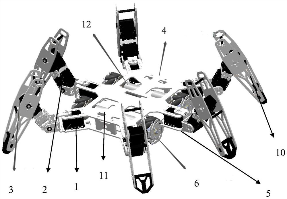
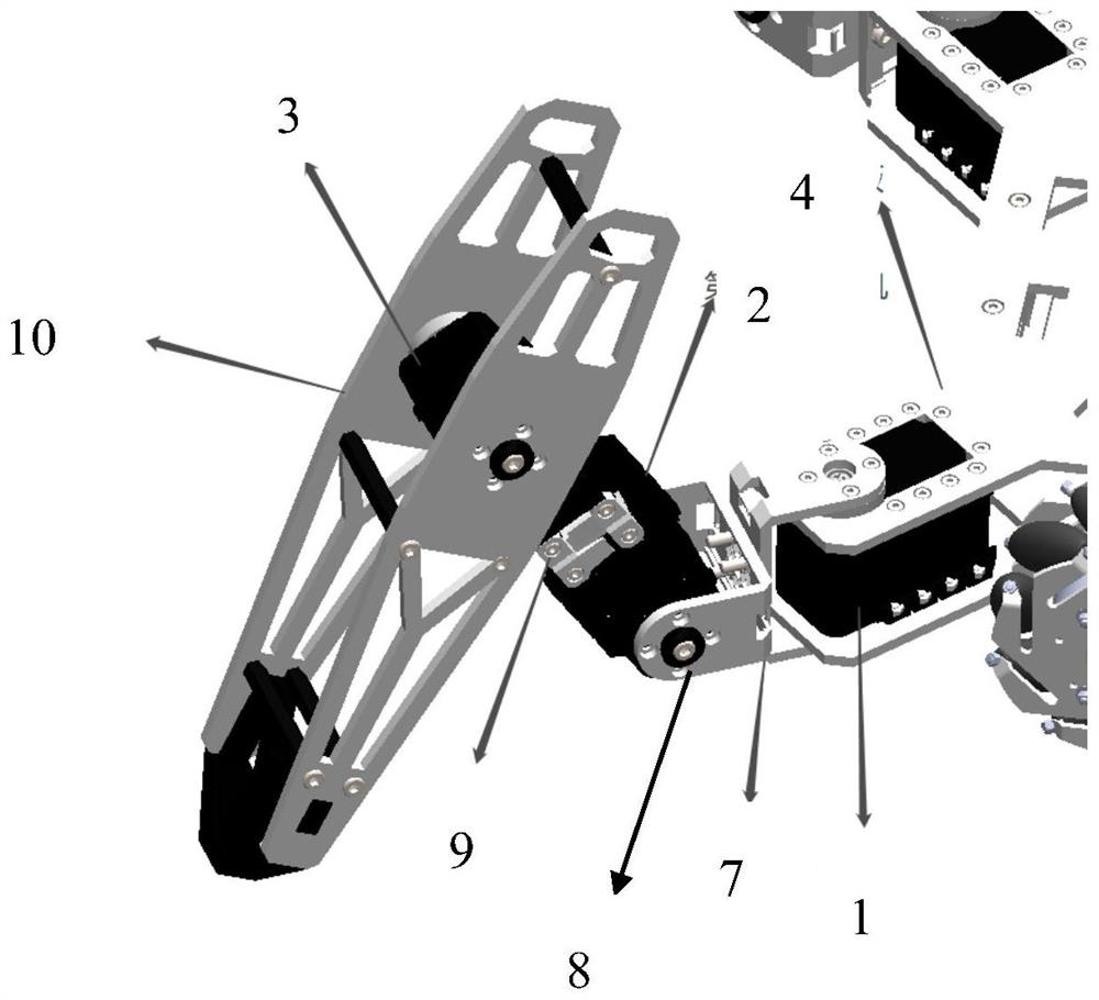
[0030] The fuselage of the multifunctional foot changing robot of the present embodiment is made up of three parts: main body, six mechanical legs and four mecanum wheels 6, as figure 1 shown. Its main body looks exactly like an H-shaped trolley chassis, and is formed by connecting two upper and lower plates of a hexagon with a symmetrical structure. The main body is used to connect and carry. On the upper board 4, as the installation control board, the fixed surface of the battery is also the installation and connection position of six first high-voltage steering gears 1 in the middle of the two boards. And four mecanum wheels 6 are hidden in the bottom of the main body, and the wheels are symmetrically distributed, connected on four motors 12 connected and installed on the lower plate, and the motor adopts bolt connection to be fixed on the lower plate.

[0031] The shape of the main body is an octagon with central axis symmetry. On its left and right sides, a machine leg ...

Embodiment 2

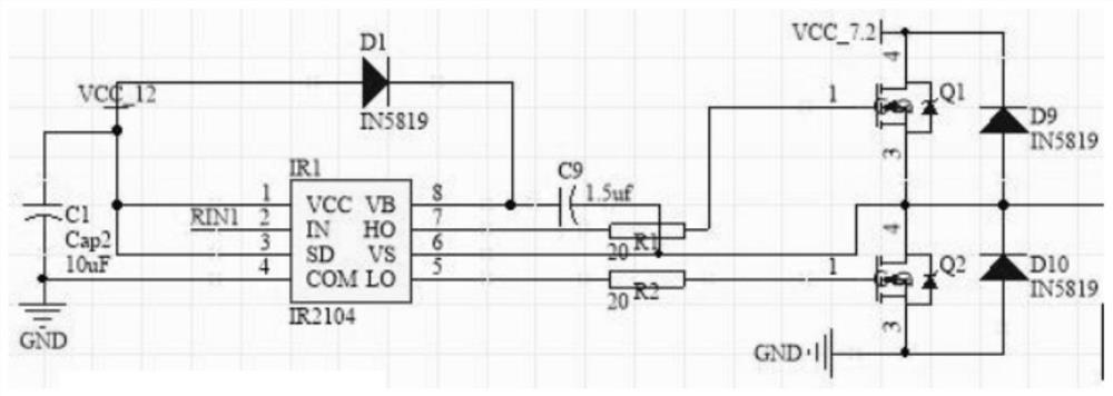
[0036] This embodiment is the design of the control system of the multi-functional variable foot robot. The control system design of the leg-wheel hybrid hexapod robot chooses embedded as the main processing system. The hardware part includes STM32F4ARM control board, power module, temperature and humidity sensor, MPU6050 six-axis sensor, 2.4G module nRF24L01, motor, steering gear, steering gear control board, motor drive module, camera 11 and transmitter. The overall framework of the hardware part of the control system is as follows: Figure 5 shown.

[0037] The main control system is composed of LPC546 and Raspberry Pi 4B: LPC546 is used as a motion control system; Raspberry Pi is used as a server to send or receive data to the client.

[0038] 1) Main control chip

[0039] This project chooses the Raspberry Pi series as the core development platform. Raspberry Pi is a micro-card computer with the size of a bank card. It can run Linux systems and windows IOT systems, and...


PUM


Abstract

The invention discloses a multifunctional foot-changing robot which takes Raspberry Pi 4B as a main control board and is divided into three forms, namely a six-foot form, a four-foot form and a wheel type form. An image is obtained through a COMS camera, robot joints are controlled through a high-voltage bus steering engine, and finally, conversion from a wheel type to a foot type of the robot is achieved, and a QT upper computer is developed to conduct movement control and remote image transmission on the multi-foot robot. The robot can change the number of feet to adapt to different environments in the process of judging the terrain and task conditions; and when the six-foot form is changed into the four-foot form or the wheel form, the remaining two feet are changed into the mechanical arm state, and complex sampling and carrying work can be conducted, so that the adaptability and stability of the robot in different environments are improved. The multi-foot robot has extremely high capability of adapting to severe terrain environments, and can replace people to autonomously work in dangerous or unreachable extreme environments, such as post-disaster rescue, interstellar exploration, military reconnaissance, volcano monitoring, antiriot and anti-terrorism occasions.

Description

technical field [0001] The invention relates to the field of robots, and relates to a multifunctional foot-changing robot. Background technique [0002] Disaster relief robots are mainly used to clean up disaster sites, and at the same time take into account the functions of investigation and communication. In disaster rescue, rescuers have only a very short time (about 48 hours) to find survivors in the collapsed ruins, otherwise the chance of finding survivors is almost zero. In this urgent and dangerous environment, disaster relief robots can provide assistance to rescuers. Therefore, the use of disaster relief robots with autonomous intelligence for "search and rescue" (SAR) survivors in dangerous and complex disaster environments is an emerging and challenging field in robotics. [0003] In China, the research on disaster robots has just started, but it is progressing rapidly. The Shenyang Institute of Automation, Chinese Academy of Sciences developed a snake-like ro...

Claims


Application Information

Patent Timeline
Patent Type & Authority Applications(China)
IPC IPC(8): B62D57/028B25J11/00B62D57/032
CPCB62D57/028B25J11/00B62D57/032
Inventor 孙静林灿辉卓祖帆马怡琛陈晓明
Owner XIAN UNVERSITY OF ARTS & SCI
Why Eureka
Try Eureka