Ecological environment-friendly aeration tank for sewage treatment

A sewage treatment and aeration tank technology, applied in the field of aeration tanks, can solve problems affecting normal use, non-environmental protection, and affecting work quality, and achieve the effects of improving work efficiency, improving connectivity, and good sealing

Inactive Publication Date: 2021-12-24
江苏科闻环保科技有限公司
View PDF11 Cites 1 Cited by
  • Summary
  • Abstract
  • Description
  • Claims
  • Application Information

AI Technical Summary

Problems solved by technology

[0004] 1. Patent document CN113233620A discloses an environmentally friendly aeration device for chemical sewage treatment, "including a first aeration mechanism and a second aeration mechanism. When the device is working, the sewage enters the aeration tank from the water inlet, and the gas pressure pump will The external air is compressed and enters the air plate assembly, which can evenly distribute the air in the air outlet to the aeration tank to the maximum extent. In addition, the fan installed above the air plate assembly can further disperse the air flowing out of the air outlet into smaller The air bubbles further increase the contact area between the air and the sewage. In addition, the first impeller can stir and mix the bottom of the aeration tank with the upper sewage, and the second impeller can stir the upper sewage and beat the sewage into the air, and the water splash dissolves in the air After more oxygen falls into the water again, the electric telescopic rod can adjust the height of the second impeller according to the depth of the sewage in the aeration tank, so as to achieve the best treatment effect", but this device does not have good sewage treatment Function, if the sewage is directly discharged into the aeration tank, it will easily pollute the tank, which will affect the normal use;
[0005] 2. The patent document CN108862908A discloses an ecological environment-friendly sewage treatment equipment, "including the water inlet pipe, and also includes the coarse filter tank, the fine filter tank, the anaerobic tank, the first anoxic tank, the aerobic tank, the second Anoxic pool, membrane pool and water outlet pipe, one end of the water inlet pipe is connected to the sewage pool, the other end is connected to the coarse filter pool, the aerobic pool is connected to the first anoxic pool through the return pipe, and the inner wall of the coarse filter pool is far away from the fine filter pool. AC electromagnet, the lower end of the AC electromagnet is provided with a metal holding box, and the fine filter tank and the anaerobic tank are connected through a fine filter pipe; flushing device; the first filter membrane and the second filter membrane are arranged in the membrane pool; the sewage undergoes a series of sewage treatment processes, so as to realize the comprehensive purification treatment of sewage and improve the purification degree of sewage", but the device has no effect on sewage The treatment method is relatively simple, and it is difficult to carry out multi-layer treatment of sewage, which affects the quality of work;
The environmentally friendly aeration device for chemical sewage treatment, through the design of sub-gears, driven gears, driving gears, sub-pipes, central pipes and outer discharge pipes, makes this device only need a motor and fan to cover the air when it is in use. The entire aeration tank aerates the sewage, thereby reducing the use of equipment, greatly reducing the consumption of electric energy and wind energy, and reducing the cost of sewage treatment, making the device more environmentally friendly and improving the efficiency of the device. Practicality", but this device does not have the function of recycling, not only the processing quality is low, but also it is easy to cause waste, so it does not have good environmental protection

Method used


Image

  • Ecological environment-friendly aeration tank for sewage treatment
  • Ecological environment-friendly aeration tank for sewage treatment
  • Ecological environment-friendly aeration tank for sewage treatment

Examples


Embodiment 1

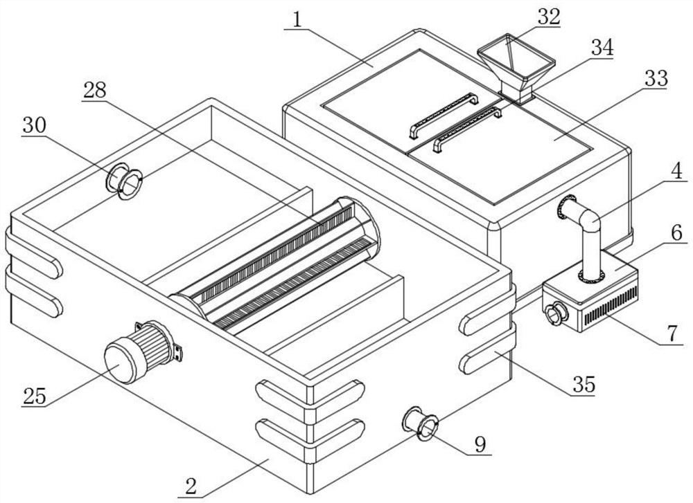
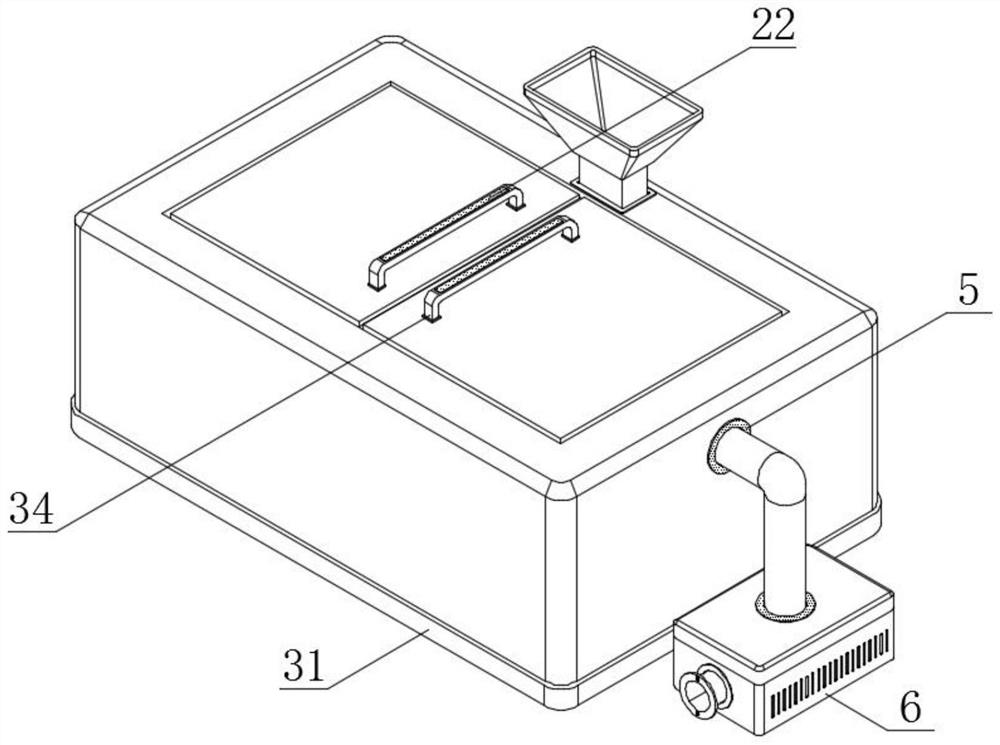
[0042] see figure 1 and Figure 8 , an embodiment provided by the present invention: an aeration tank for ecological environment-friendly sewage treatment, including a working box 1 and an aeration tank 2, a working box 1, aeration tank 2 and a driving gear 3, and a part of the working box 1 An aeration tank 2 is arranged on the side, and a driving gear 3 is arranged at the bottom of the inner middle part of the working box 1; a water inlet pipe 4 is arranged above the middle part of the surface of the working box 1, and a sealing ring 5 is arranged at the intersection of the water inlet pipe 4 and the working box 1 The bottom end of the water inlet pipe 4 is connected with a placement box 6, and the surface of the placement box 6 is provided with several cooling strips 7, and the inside of the placement box 6 is provided with a first water pump 8, the input end of the first water pump 8 and the aeration tank 2 Connecting pipes 9 are installed on the bottom of the middle of t...

Embodiment 2

[0045] see image 3 , Figure 4 , Figure 5 and Figure 6 , an embodiment provided by the present invention: an aeration tank for ecological and environment-friendly sewage treatment, comprising a working box 1, one side of the inner top wall and the inner bottom wall of the working box 1 is equipped with a fixing clip 11, and the fixing clip 11 The internal thread of the fixed plate 12 is connected with the fixed plate 12, and the intersection of the fixed clip 11 and the fixed plate 12 is threaded with a fastening knob. Adsorption plate 14 is installed, and the top of driving gear 3 is equipped with first drive motor 15, and the output end of first drive motor 15 penetrates and is connected with the inner side wall of work box 1, and the surface of driving gear 3 is meshed with crawler teeth 16, crawler belt The top inside the tooth 16 is meshed with a movable gear 17, the bottom of the driving gear 3 and the movable gear 17 is equipped with a transmission rod 18, and the...

Embodiment 3

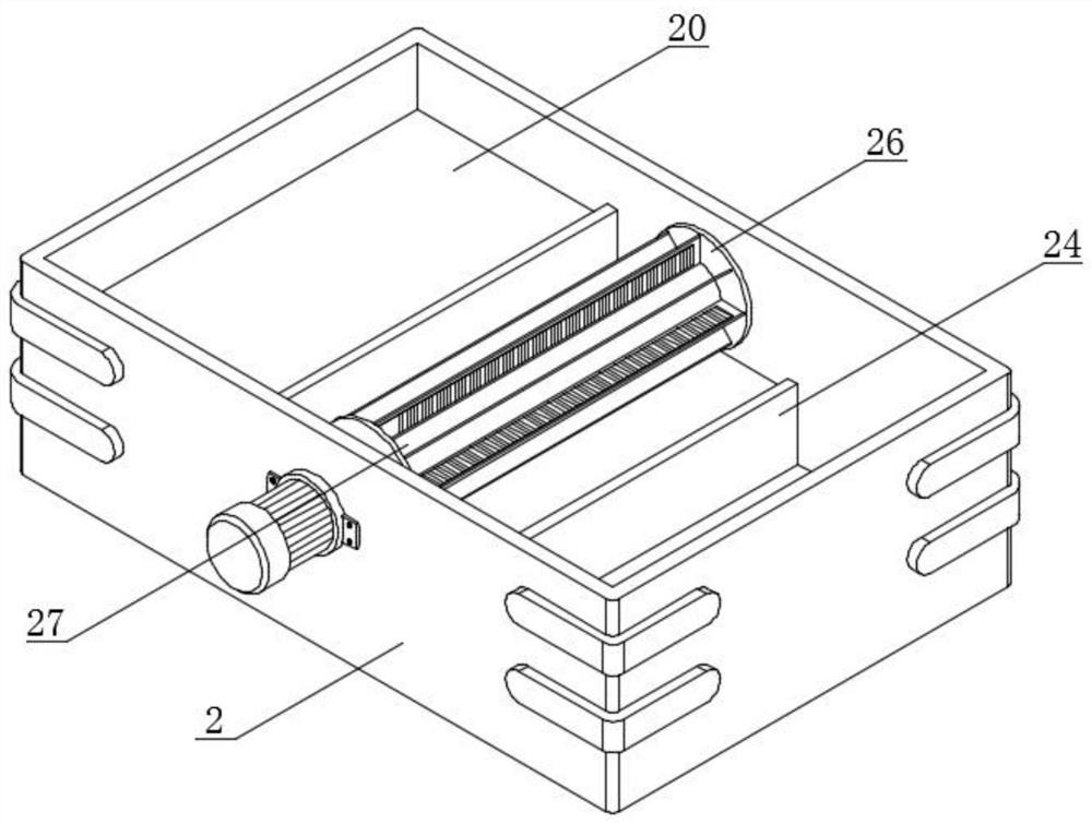
[0048] see figure 2 and Figure 7 , an embodiment provided by the present invention: an aeration tank for ecological environment-friendly sewage treatment, including an aeration tank 2, a first splitter tank 20 is installed on one side of the aeration tank 2, and the inside of the aeration tank 2 The second distributing tank 21 is installed in the middle, and the third distributing tank 23 is installed on the other side inside the aeration tank 2, and the first distributing tank 20 and the second distributing tank 21 and the second distributing tank 21 and the third distributing tank 23 Limiting baffles 24 are installed at the intersections of the aeration tanks 2, reinforcement strips 35 are installed on the surface of the aeration tank 2, and the number of reinforcement strips 35 is four groups. A second drive motor 25 is installed on the side, and the output end of the second drive motor 25 runs through the inner wall of the aeration tank 2 to install a limit plate 26. Th...


PUM


Abstract

The invention discloses an ecological environment-friendly aeration tank for sewage treatment, the ecological environment-friendly aeration tank comprises a working box, an aeration tank and a driving gear, the aeration tank is arranged on one side of the working box, and the driving gear is arranged at the bottom of the middle part in the working box; a water inlet pipe is arranged above the middle of the surface of the working box, and a sealing ring is arranged at the intersection of the water inlet pipe and the working box. Through the arrangement of the working box and the aeration tank, when a worker needs to treat sewage, water in the aeration tank can be conveniently conveyed into the working box by the worker through the matched work of the water inlet pipe, the first water pump and the connecting pipeline, so that the sewage can be conveniently treated in the later period; with the arrangement of the sealing ring, the structure is enabled to have relatively good sealing performance, a relatively good placement structure can be provided for the first water pump through matched work of the placement box and the heat dissipation strips, and heat dissipated when the first water pump works can be discharged in time, so that the overall connectivity of the device is improved, and the sewage treatment quality is further improved.

Description

technical field [0001] The invention relates to the technical field of aeration tanks, in particular to an ecological and environment-friendly aeration tank for sewage treatment. Background technique [0002] The aeration tank is a structure that uses the activated sludge method for sewage treatment. A certain sewage residence time is provided in the pool to meet the oxygen required by aerobic microorganisms and the mixing conditions for full contact between sewage and activated sludge. It is often difficult to treat large amounts of sewage. The aeration tank is used, but the existing aeration tank still has certain deficiencies in actual use. [0003] An existing aeration tank for sewage treatment. The existing defects are: [0004] 1. Patent document CN113233620A discloses an environmentally friendly aeration device for chemical sewage treatment, "including a first aeration mechanism and a second aeration mechanism. When the device is working, the sewage enters the aerat...

Claims


Application Information

Patent Timeline
Patent Type & Authority Applications(China)
IPC IPC(8): C02F3/12C02F9/14
CPCC02F3/12C02F9/00C02F2203/006C02F2303/14C02F1/001C02F1/28C02F1/5281C02F2303/16Y02W10/10
Inventor 徐庆惠陈香吉映臣陈尹
Owner 江苏科闻环保科技有限公司
Why Eureka
Try Eureka