Novel cantilever steel scaffold and construction process thereof

A scaffolding and cantilevering technology, which is applied to the accessories of scaffolding, scaffolding supported by house structure, and construction, etc., can solve the problem of uneven stress on I-beams and floors, difficulty in masonry construction of cantilevered layers, and increase the limitations of scaffolding. and other problems, to achieve the effect of easy disassembly and recycling, repeated turnover, easy automatic correction, and stable assembly

Active Publication Date: 2021-12-24
THE SIXTH CONSTR CO LTD OF CHINA NAT CHEM ENG
View PDF5 Cites 3 Cited by
  • Summary
  • Abstract
  • Description
  • Claims
  • Application Information

AI Technical Summary

Problems solved by technology

[0003] During the actual assembly of the current cantilevered steel scaffolding, positioning parts are generally embedded on the floor to quickly locate and connect the I-beams. However, even if the reserved holes are filled in the later stage, there will be hidden dangers of water leakage, resulting in The masonry construction of the cantilevered floor is difficult, and the force between the I-beam and the floor is not uniform, and the support force between the external scaffold and the I-beam between the floors is easy to incline to the outer wall, reducing the cantilever components Due to the excessive vertical load on the upper part, the cantilever beam and the root of the cantilever slab will be torn, and there may even be the danger of overturning and collapsing. After the scaffold is assembled, anchor bolts and steel wire ropes are often required for reinforcement. The connection between the embedded parts and the wall will cause greater damage to the wall and increase the limitations of scaffolding reinforcement

Method used


Image

  • Novel cantilever steel scaffold and construction process thereof
  • Novel cantilever steel scaffold and construction process thereof
  • Novel cantilever steel scaffold and construction process thereof

Examples


Embodiment 1

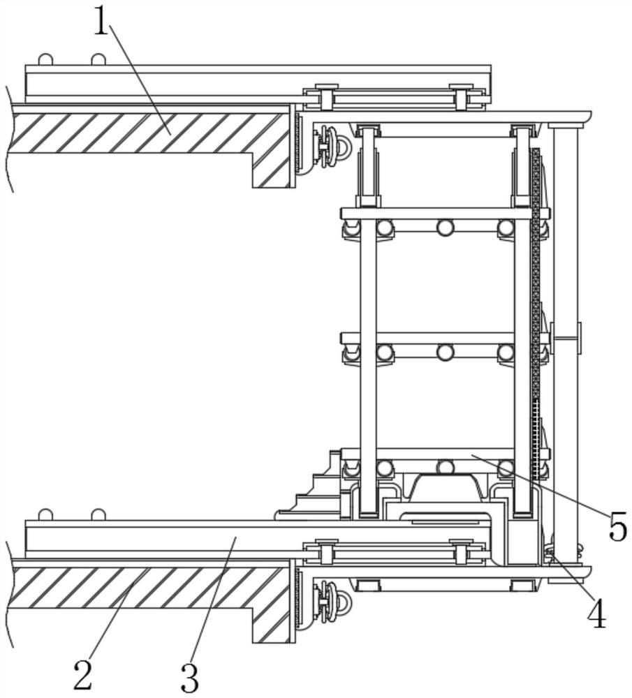
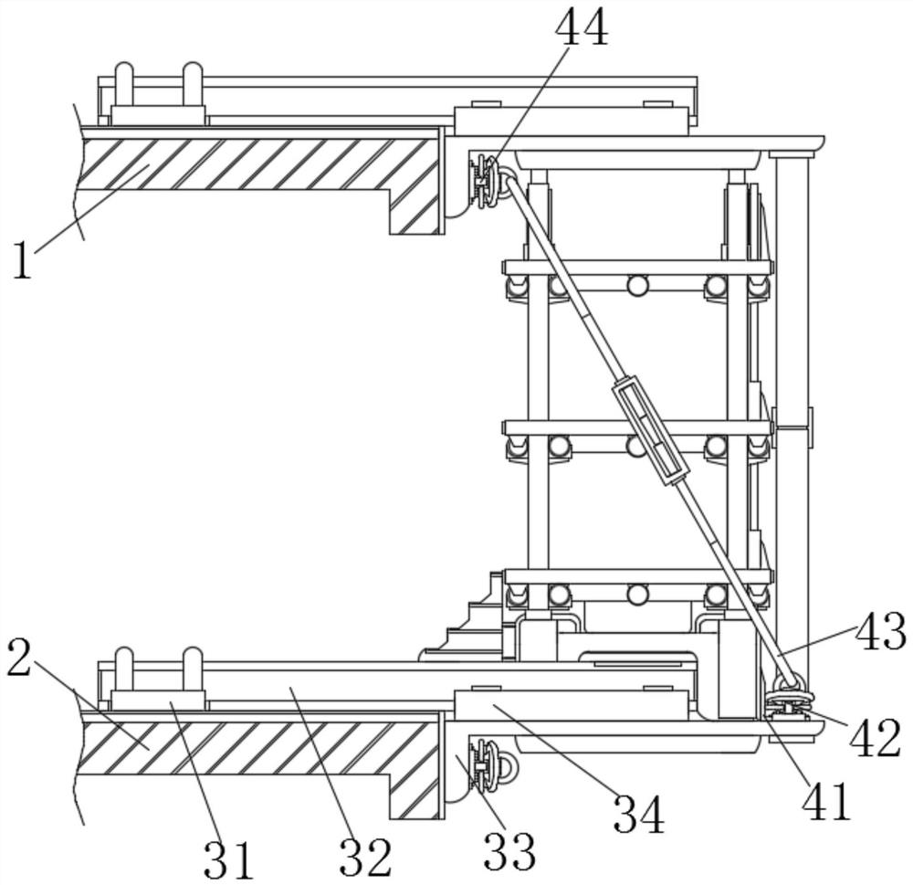
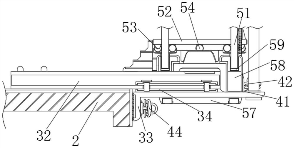
[0045] Example 1, such as image 3 As shown, when the scaffolding is fixed on the top of the I-shaped steel 32, the connection between the first ear plate 42 and the platform seat 58 can be fixed through the connecting support 41, so that the turnbuckle 43 can be installed on the L-shaped support plate 33 as a whole at the same time. The designed main structure is reinforced and supported, which greatly improves the stability of the outer scaffold, and the sleeve 59 provided by the cap seat 58 is matched with the trapezoidal fixing seat and the trapezoidal fixing groove to further improve the relationship between the scaffold and the I-shaped steel 32 structure. The tightness and positioning effect of the connection between them.

Embodiment 2

[0046] Example 2, such as Figure 5-6 As shown, the I-shaped steel 32 can be provided with a positioning hole at a designated position on the ground in advance, and the sliding kit 34 can be slid into the outside of the I-shaped steel 32 and fixed by positioning bolts, and then the L-shaped support plate 33 and the sliding The set 34 is welded into an integrated structure, so that the integrated structure of the I-shaped steel 32, the L-shaped support plate 33 and the sliding set 34 can be quickly contacted and positioned with the upper floor 1 and the lower floor 2, providing the structure between floors. fit and support strength.

[0047] Working principle: When the device is in use, the integrated structure of the I-shaped steel 32, the sliding set 34 and the L-shaped support plate 33 can be used to quickly position and splice the I-shaped steel 32 with the upper floor 1 or the lower floor 2 to promote The overall supporting force of the I-shaped steel 32 is more uniform, ...


PUM


Abstract

The invention discloses a novel cantilever steel scaffold and a construction process thereof. The novel cantilever steel scaffold comprises an upper floor, a lower floor, a positioning and supporting mechanism, a cantilever reinforcing mechanism and a scaffold mechanism; the positioning and supporting mechanism comprises embedded positioning pieces, four sets of I-shaped steel, L-shaped supporting plates and sliding sleeve pieces; the top of the upper floor and the top of the lower floor are each provide width two sets of I-shaped steel; and the embedded positioning pieces are embedded in the two ends of one side of the top of the interior of the upper floor and the two ends of one side of the top of the interior of the lower floor. Through mutual cooperation of the sliding sleeve pieces and the L-shaped supporting plates, prefabricated pieces and the I-shaped steel can be welded into a whole in advance, so that the binding faces for supporting and positioning of external walls and internal walls of the upper floor and the lower floor are reinforced through connection of the sliding sleeve pieces and the L-shaped supporting plates, a bidirectional supporting system is formed between the structure and the walls, and the load and stress strength of a scaffold body above the I-shaped steel are greatly enhanced.

Description

technical field [0001] The invention relates to the technical field of building construction, in particular to a novel cantilevered steel scaffold and a construction process thereof. Background technique [0002] With the rapid development of urban construction and the increasing number of high-rise and super high-rise buildings, the safety and quality requirements for building construction are also getting higher and higher. The construction environment is becoming more and more complex. In order to meet the needs of structural construction and exterior decoration construction, cantilevered The outer scaffolding of steel pipe fasteners has been widely used because of its wide adaptability, strong bearing capacity, and convenient erection and dismantling. [0003] During the actual assembly of the current cantilevered steel scaffolding, positioning parts are generally embedded on the floor to quickly locate and connect the I-beams. However, even if the reserved holes are fil...

Claims


Application Information

Patent Timeline
Patent Type & Authority Applications(China)
IPC IPC(8): E04G3/18E04G3/20E04G5/04E04G5/08
CPCE04G3/18E04G3/20E04G5/04E04G5/046E04G5/08E04G5/006E04G5/007
Inventor 旃宏方伟袁兆明韩涛蔡来瑜王傲曾少毅黄志刚
Owner THE SIXTH CONSTR CO LTD OF CHINA NAT CHEM ENG
Why Eureka
Try Eureka