
Oil supply assembly, compressor and control method

A technology of compressors and components, applied in the field of compressors, can solve the problems of increased power consumption of compressors, difficulty in oiling, low cooling capacity, etc., and achieve the effect of reducing oil discharge rate and widening the speed range

Pending Publication Date: 2021-12-24
ZHUHAI LANDA COMPRESSOR +1
View PDF9 Cites 0 Cited by
  • Summary
  • Abstract
  • Description
  • Claims
  • Application Information

AI Technical Summary

Problems solved by technology

[0002] The fan speed of the oil supply assembly of the existing rolling rotor compressor is the same as the crankshaft rotation speed of the compressor, and the oil supply is limited by the crankshaft speed. There is a demand for the compressor to operate at an ultra-low speed in the market, such as taking into account the heat management of the whole vehicle For air conditioners of new energy vehicles, when it is only necessary to cool down the power battery under certain conditions in some models, the required cooling capacity is very low, which is quite different from the required cooling capacity when running at full load. It needs 5rps. The minimum working speed of the existing compressor motor generally requires more than 10rps. If it is lower than 10rps, it will be difficult to oil and there is a risk of poor lubrication.
In addition, the oil discharge rate of the existing compressor increases faster with the increase of the compressor motor speed, and to reduce the oil discharge rate, an additional oil separation device is required, which will increase the power consumption of the compressor

Method used


Image

  • Oil supply assembly, compressor and control method
  • Oil supply assembly, compressor and control method
  • Oil supply assembly, compressor and control method

Examples


Embodiment Construction

[0039] In order to make the purpose, technical solution and advantages of the present invention clearer, the technical solution of the present invention will be clearly and completely described below in conjunction with specific embodiments of the present invention and corresponding drawings. Apparently, the described embodiments are only some of the embodiments of the present invention, but not all of them. Based on the embodiments of the present invention, all other embodiments obtained by persons of ordinary skill in the art without making creative efforts belong to the protection scope of the present invention.

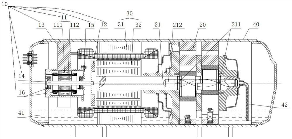
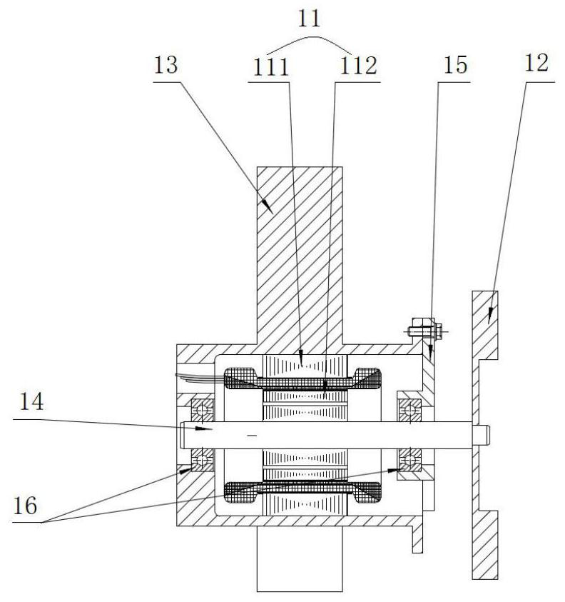
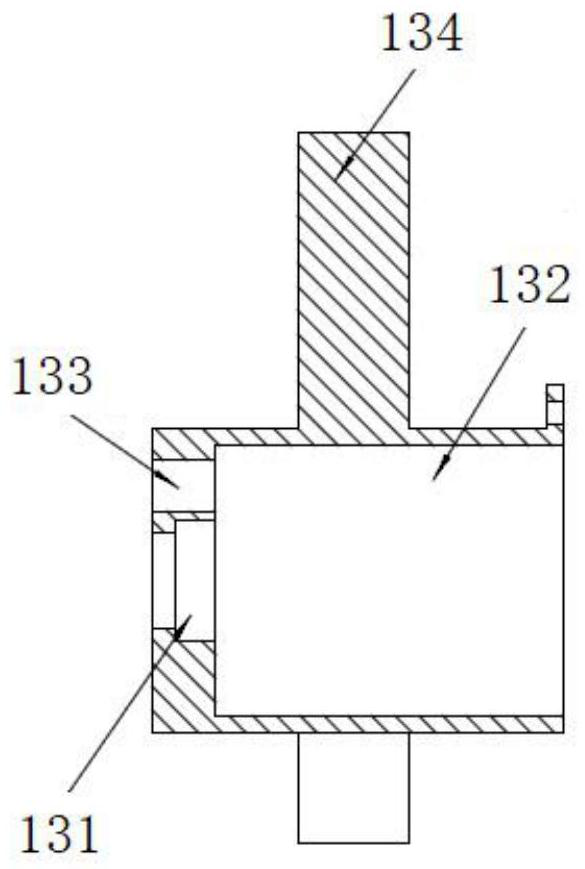
[0040] combine Figure 1 to Figure 8 As shown, the present invention provides an oil supply assembly, the oil supply assembly 10 includes a fan 12, the fan 12 is configured to be able to adjust the pressure difference at both ends of the crankshaft center oil hole 212 of the crankshaft 21 according to the real-time rotational speed of the compressor motor 30, The...


PUM


Abstract

The invention provides an oil supply assembly, a compressor and a control method. The oil supply assembly comprises a fan, and the fan is configured to adjust the pressure difference between the two ends of a crankshaft center oil hole according to the real-time rotating speed of a compressor motor so that the crankshaft center oil hole can be normally oiled when the compressor motor runs. The technical problems that the rotating speed of a fan of an oil supply assembly of a compressor is consistent with the rotating speed of a crankshaft of the compressor, the oil supply amount is limited by the rotating speed of a crankshaft, and consequently oil supply is not smooth during operation of the compressor are solved, the rotating speed range of the compressor motor is widened, and on the other hand, the oil spitting rate of the compressor can be reduced.

Description

technical field [0001] The invention belongs to the technical field of compressors, and in particular relates to an oil supply assembly, a compressor and a control method. Background technique [0002] The fan speed of the oil supply assembly of the existing rolling rotor compressor is the same as the crankshaft rotation speed of the compressor, and the oil supply is limited by the crankshaft speed. There is a demand for the compressor to operate at an ultra-low speed in the market, such as considering the heat management of the whole vehicle The air conditioner of new energy vehicles, under certain conditions of some models, only needs to cool down the power battery, the required cooling capacity is very low, which is very different from the required cooling capacity when running at full load. At this time, the working speed of the compressor motor even only It needs 5rps. The minimum working speed of the existing compressor motor generally requires more than 10rps. If it i...

Claims


Application Information

Patent Timeline
IPC IPC(8): F04C29/02F04C23/02F04C28/28F04D27/00
CPCF04C29/021F04C23/02F04C28/28F04D27/004
Inventor 吴禄李建宾赵旭敏李运飞
Owner ZHUHAI LANDA COMPRESSOR
Learn More