
Embedded planetary speed reducing mechanism

A planetary deceleration and embedded technology, which is applied to clockwork mechanisms, mechanical equipment, vehicle gearboxes, etc., can solve problems such as changing the lifting speed, limited transmission ratio improvement, and self-heavy mass, so as to increase the load and increase the transmission ratio , compact effect

Active Publication Date: 2021-12-31
HENAN DONGQI MACHINERY
View PDF7 Cites 2 Cited by
  • Summary
  • Abstract
  • Description
  • Claims
  • Application Information

AI Technical Summary

Problems solved by technology

[0003] The deceleration mechanisms of existing cranes are mostly fixed one-stage deceleration or two-stage deceleration. The volume is large and the mass is heavy. The deceleration performance per unit volume cannot be effectively improved, and the lifting speed cannot be changed with the mass of the lifting weight. The transmission ratio The lifting is limited, it is impossible to realize heavy-load slow travel and light-load fast travel, and the driving power cannot be fully utilized; the embedded planetary reduction mechanism has not been applied in the field of cranes, because its transmission ratio is limited and cannot meet the above-mentioned speed change demand, and the size is also limited by the transmission ratio, and it is impossible to make a breakthrough on the original basis and take advantage of its own large transmission ratio.

Method used


Image

  • Embedded planetary speed reducing mechanism
  • Embedded planetary speed reducing mechanism
  • Embedded planetary speed reducing mechanism

Examples


Embodiment Construction

[0046] Hereinafter, the present invention will be described in detail with reference to the drawings and examples. It should be noted that, in the case of no conflict, the embodiments of the present invention and the features in the embodiments can be combined with each other.

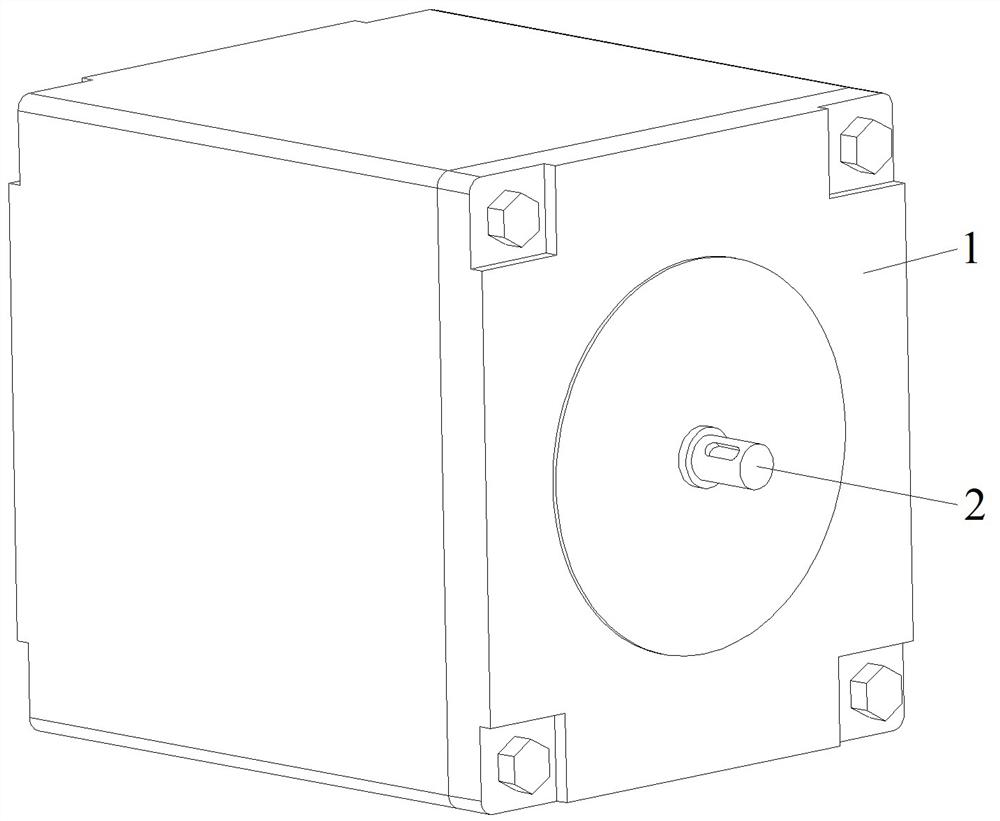
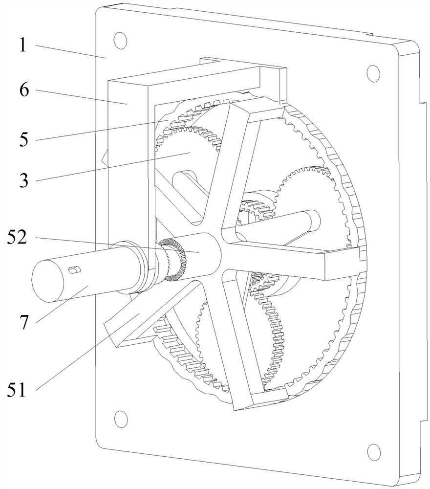
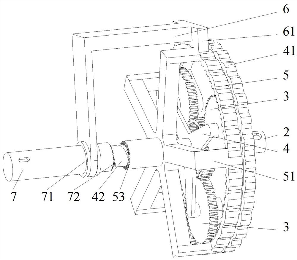
[0047] Such as Figure 1-14 The shown embodiment of the present invention is an embedded planetary reduction mechanism, which includes a housing 1, a sealing groove 12, a chute 11, and a planetary groove 13 are arranged on the housing 1, and the primary planetary gear is arranged in the housing 1 gear train and secondary planetary gear train;

[0048] The primary planetary gear system includes planetary gear Ⅱ3, planetary carrier Ⅱ4, ring gear 5, and input ring gear 22, wherein the input ring gear 22 is the sun gear of the primary planetary gear system, and planetary carrier Ⅱ4 includes planetary gear 41, planetary output shaft 42;

[0049] The planetary output shaft 42 is pivotally connected with t...


PUM


Abstract

The invention relates to an embedded planetary speed reducing mechanism. A sealing groove, a sliding groove and a planetary groove are formed in a shell; a primary planetary gear train and a secondary planetary gear train are arranged in the shell; the primary planetary gear train comprises planetary gears II, a planetary carrier II, an inner gear ring and an input gear ring, the input gear ring is a sun gear of the primary planetary gear train, and the planetary carrier II comprises a planetary gear ring and a planetary output shaft; the planet output shaft is connected with three cantilevers on the inner wall of the planet gear ring through three cantilevers and shafts, and the planet gears II are arranged on the planet carrier II in a rotatable annular array mode through the shafts; the input gear ring is the input end of the primary planetary gear train, and the input gear ring is the output end of the secondary planetary gear train; and the output module comprises a planet output shaft, a gear ring output shaft barrel and a terminal output shaft, a selection clamping module comprises a sliding groove and a limiting frame, the insertion end of the limiting frame is limited in the sliding groove in a sliding mode, a brake block of the limiting frame is made to clamp the inner gear ring or the planet gear ring, and output is conducted outwards through the planet output shaft or the gear ring output shaft barrel.

Description

technical field [0001] The invention relates to the technical field of an embedded planetary reduction mechanism, in particular to an embedded planetary reduction mechanism. Background technique [0002] At present, a crane refers to a multi-action hoisting machine that lifts vertically and transports heavy objects horizontally within a certain range. The crane mainly includes hoisting mechanism, operating mechanism, luffing mechanism, slewing mechanism and metal structure, etc.; the hoisting mechanism is the basic working mechanism of the crane, which is generally composed of a motor, a reducer, a brake, a force arm and a numerical control system. Reduce the output shaft speed of the motor through the reducer, increase the output torque, and lift the heavy object. [0003] The deceleration mechanisms of existing cranes are mostly fixed one-stage deceleration or two-stage deceleration. The volume is large and the mass is heavy. The deceleration performance per unit volume c...

Claims


Application Information

Patent Timeline
Patent Type & Authority Applications(China)
IPC IPC(8): F16H3/70F16H3/72F16H57/10F16H57/08F16H57/023F16H57/029B66D1/22
CPCF16H3/70F16H3/72F16H3/724F16H57/10F16H57/08F16H57/082F16H57/023F16H57/029B66D1/225F16H2003/447F16H2200/2007F16H2200/2033
Inventor 张春丽王立建王智军李先阳李元恒刘文明傅博张德龙
Owner HENAN DONGQI MACHINERY
Learn More