Tail gas incinerator of sulfur recovery, waste heat utilization and tail gas treatment integrated device

A technology for exhaust gas treatment and combined device, which is applied to incinerators, combustion methods, combustion types, etc., can solve the problems of inconvenient disassembly and maintenance by maintenance personnel, no exhaust gas control, inconvenient internal temperature control of incinerators, etc., so as to facilitate sufficient incineration. , to achieve the effect of full combustion, easy disassembly and maintenance

Inactive Publication Date: 2021-12-31
陆大国
View PDF1 Cites 0 Cited by
  • Summary
  • Abstract
  • Description
  • Claims
  • Application Information

AI Technical Summary

Problems solved by technology

[0007] The object of the present invention is to provide a tail gas incinerator of a combined device for sulfur recovery and waste heat utilization tail gas treatment. The gas outlet and gas parts are abutted against each other, the gas outlet and gas parts are embedded in the cavity, and the discharge parts and gas delivery parts pass through The external bolts are fixed to the cavity, which solves the problems that the existing exhaust gas incinerator does not have a structure for controlling the exhaust gas, it is inconvenient for maintenance personnel to disassemble and repair, and it is inconvenient for the internal temperature control of the incinerator

Method used


Image

  • Tail gas incinerator of sulfur recovery, waste heat utilization and tail gas treatment integrated device
  • Tail gas incinerator of sulfur recovery, waste heat utilization and tail gas treatment integrated device
  • Tail gas incinerator of sulfur recovery, waste heat utilization and tail gas treatment integrated device

Examples


Embodiment Construction

[0033] The following will clearly and completely describe the technical solutions in the embodiments of the present invention with reference to the drawings in the embodiments of the present invention.

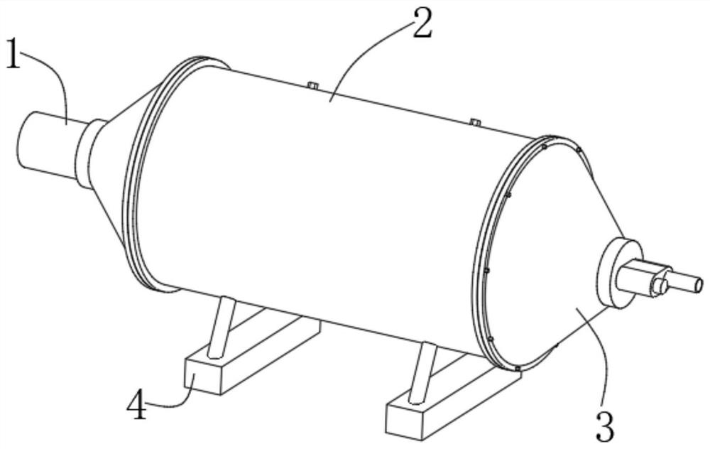
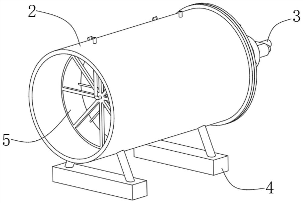
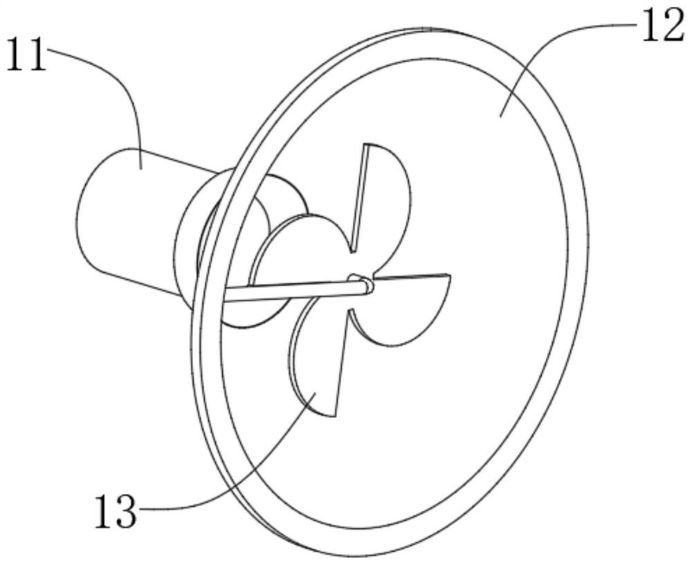
[0034] see Figure 1-7 As shown, the present invention is a tail gas incinerator of a combined device for sulfur recovery and waste heat utilization tail gas treatment, including a discharge part 1, a cavity body 2, a gas delivery part 3, a support seat 4 and an incineration part 5, and one end of the cavity body 2 is fixedly connected There is a discharge piece 1, the other end of the cavity 2 is fixedly connected with a gas delivery piece 3, the bottom of the cavity 2 near both ends is fixedly connected with a support seat 4, the inside of the cavity 2 is fixedly connected with an incineration piece 5, and the discharge piece 1 and the gas transmission part 3 are fixedly connected with the cavity 2 by fixing bolts, and the incineration part 5 is embedded in the interior of t...


PUM


Abstract

The invention discloses a tail gas incinerator of a sulfur recovery, waste heat utilization and tail gas treatment integrated device, and relates to the technical field of tail gas treatment equipment. The tail gas incinerator comprises a discharging part, a cavity, a gas conveying part, supporting seats and an incineration part, the discharging part is fixedly connected to one end of the cavity, the gas conveying part is fixedly connected to the other end of the cavity, the supporting seats are fixedly connected to the positions, close to the two ends, of the bottom of the cavity, the incineration part is fixedly connected into the cavity, the discharging part and the gas conveying part are fixedly connected with the cavity through fixing bolts, the incineration part is embedded into the cavity, and a gas outlet part and a gas part are clamped. According to the tail gas incinerator of the sulfur recovery, waste heat utilization and tail gas treatment integrated device, the gas outlet part and the gas part abut against each other, the gas outlet part and the gas part are embedded into the cavity, and the discharging part and the gas conveying part are fixed to the cavity through external bolts, so that the problems that according to an existing tail gas incinerator, a tail gas control structure is not provided, disassembly and maintenance by maintenance personnel are not convenient, and internal temperature control of the incinerator is not convenient are solved.

Description

technical field [0001] The invention belongs to the technical field of tail gas treatment equipment, and in particular relates to a tail gas incinerator of a combined tail gas treatment device for sulfur recovery and waste heat utilization. Background technique [0002] Sulfur will produce tail gas in the process of processing and production, but the tail gas cannot be discharged directly into the atmosphere, and it needs to be treated before it can be discharged. This requires the use of tail gas treatment devices, but it is generally more conventional for existing incinerators. For sulfur The tail gas produced in the production process cannot be fully incinerated, so it needs to be improved; [0003] In the existing public document CN208871646U-a tail gas incinerator for sulfur recovery, the tail gas spray gun is arranged on the burner part of the tail gas incinerator, and the incinerator body is divided into a front burning area and a rear burning area, so that it can be ...

Claims


Application Information

Patent Timeline
Patent Type & Authority Applications(China)
IPC IPC(8): F23G7/06F23G5/44F23G5/50F23G5/46
CPCF23G7/06F23G5/44F23G5/50F23G5/46
Inventor 陆大国
Owner 陆大国
Why Eureka
Try Eureka