Combined cooling, heating and power generator set
A technology of combined cooling, heating and power supply and generator set, which is applied in the directions of refrigerators, refrigeration components, heat pumps, etc., can solve the problems of overflowing cold water, affecting energy utilization, and the lack of leakage alarm function of hot water absorption cold water chassis
- Summary
- Abstract
- Description
- Claims
- Application Information
AI Technical Summary
Problems solved by technology
Method used
Image
Examples
Embodiment 1
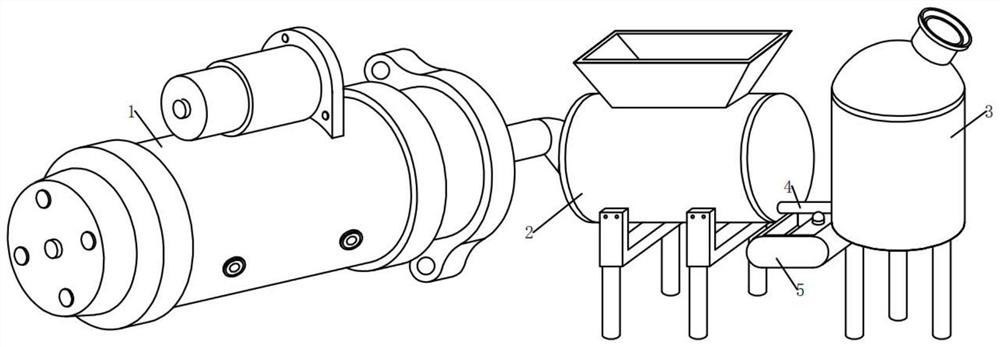
[0051] see Figure 1-4 , in an embodiment of the present invention, a generator set for combined cooling, heating and power supply, including:
[0052] A generator set 1, the right end of the generator set 1 is fixedly connected with a hot water absorption chiller box 2, and the lower part of the right end of the hot water absorption chiller box 2 is connected with a water cooling box 4 through a pipe 4;
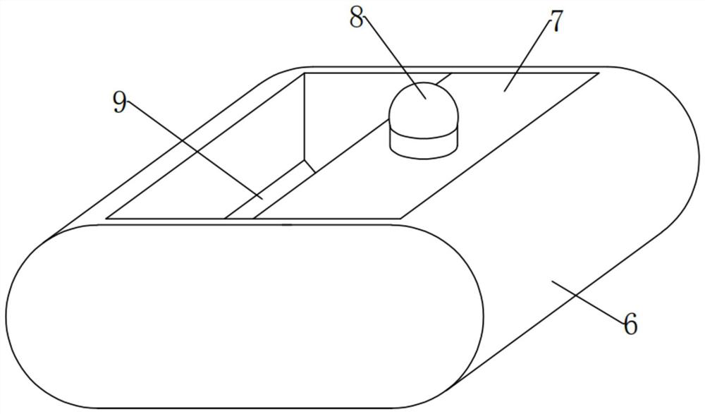
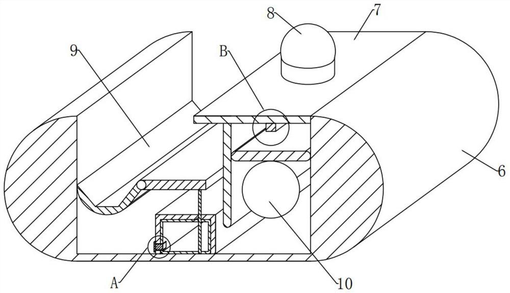
[0053] Leakage alarm assembly 5, the bottom right part of the hot water absorption type chiller box 2 and the bottom left part of the water cooling box 4 are fixedly installed before the pipeline 4 leaks on the hot water absorption type chiller box 2. The leakage alarm component 5 for alarming, the leakage alarm component 5 includes: a water receiving tank 6, a fixed plate 7, an alarm 8, a monitoring component 9 that can move in time after a water leak and a push component that can assist an alarm after a water leak 10;
[0054] The appearance of the water receiving tank 6...
Embodiment 2
[0065] see image 3 , Figure 5-6 and Figure 9 Compared with Embodiment 1, the embodiment of the present invention differs in that the monitoring component 9 includes:
[0066] Rotating shaft 11, the central position of the inner left end of the water receiving tank 6 is rotated in the front and rear horizontal direction, and the rotating shaft 11 is installed, and the front and rear ends of the rotating shaft 11 are rotatably mounted on the left end central position of the front and rear inner walls of the water receiving tank 6;
[0067] Left plate 12, left plate 12 is fixedly installed around the outer surface of the left side of rotating shaft 11. The appearance of left plate 12 is internally hollow on a longitudinal section, with a semicircle at the bottom and an inverted trapezoidal groove shape at the top. The outer surface on the left side of the top is still attached to the middle surface of the left inner wall of the water receiving tank 6 under normal conditions,...
Embodiment 3
[0085] see image 3 , Figure 7-9Compared with Embodiment 1, the embodiment of the present invention differs in that the pushing assembly 10 includes:
[0086] Slide rail 18, the left end position of the bottom side outer surface of fixed plate 7 is fixedly installed with slide rail 18 in vertical direction up and down, and the bottom tail of slide rail 18 extends to the right end upper position near limit plate 14;
[0087] The slide rail 18 here is for the convenience of providing the sliding passage on the slide plate 19, and triggering the alarm 8 to report to the police after receiving water in the water receiving tank 6 in time.
[0088] In the embodiment of the present invention, the pushing assembly 10 also includes:
[0089] Sliding plate 19, the position between the right end of slide rail 18 and the right inner wall of water receiving tank 6 slides and is installed with slide plate 19, and slide plate 19 is in the upper end position of slide rail 18 horizontally u...
PUM
 Abstract
Description
Claims
Application Information
 - R&D
- Intellectual Property
- Life Sciences
- Materials
- Tech Scout
- Unparalleled Data Quality
- Higher Quality Content
- 60% Fewer Hallucinations
Browse by: Latest US Patents, China's latest patents, Technical Efficacy Thesaurus, Application Domain, Technology Topic, Popular Technical Reports.
© 2025 PatSnap. All rights reserved.Legal|Privacy policy|Modern Slavery Act Transparency Statement|Sitemap|About US| Contact US: help@patsnap.com


