Drying equipment control method and drying system

A technology of drying equipment and control method, applied in the field of drying, can solve the problem of high energy consumption

Active Publication Date: 2022-01-04
QINGDAO HAIER AIR CONDITIONING ELECTRONICS CO LTD +2
View PDF4 Cites 3 Cited by
  • Summary
  • Abstract
  • Description
  • Claims
  • Application Information

AI Technical Summary

Problems solved by technology

[0004] The invention provides a drying equipment control method, which solves the problem of high energy consumption in the prior art

Method used


Image

  • Drying equipment control method and drying system
  • Drying equipment control method and drying system
  • Drying equipment control method and drying system

Examples


Embodiment Construction

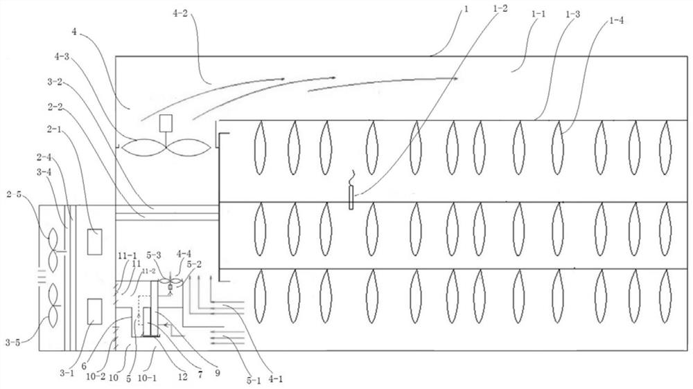
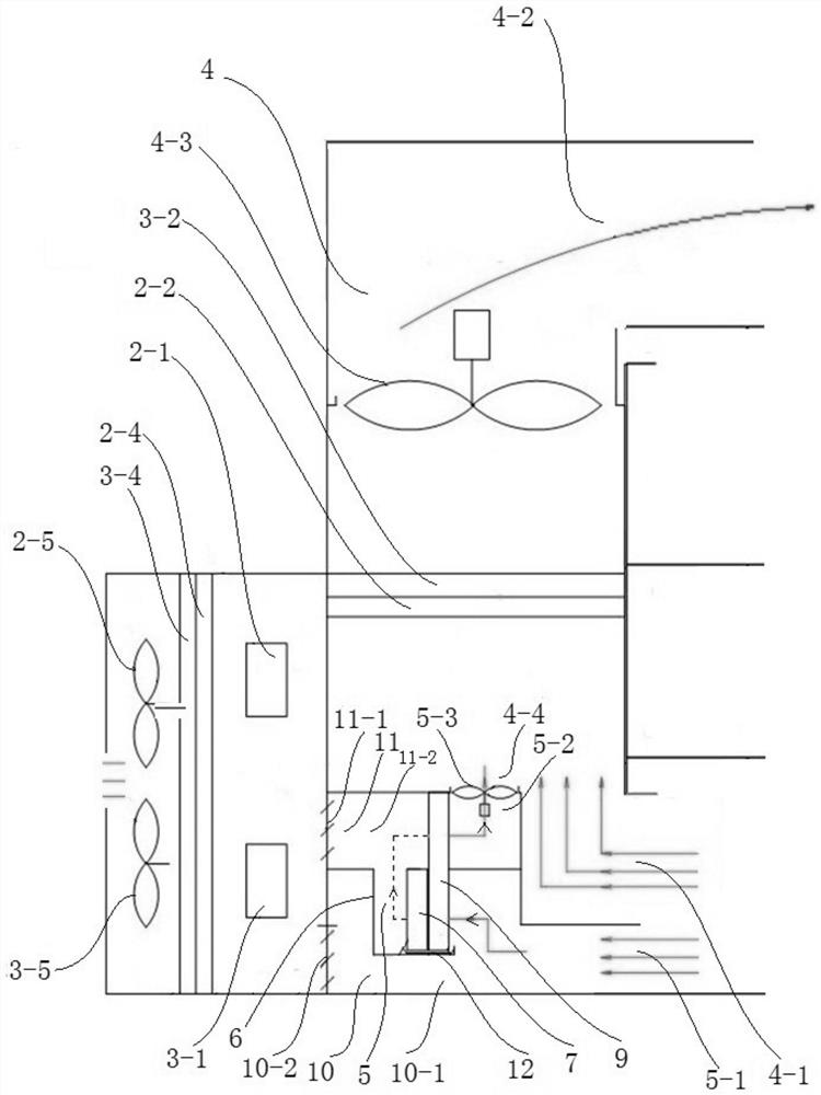
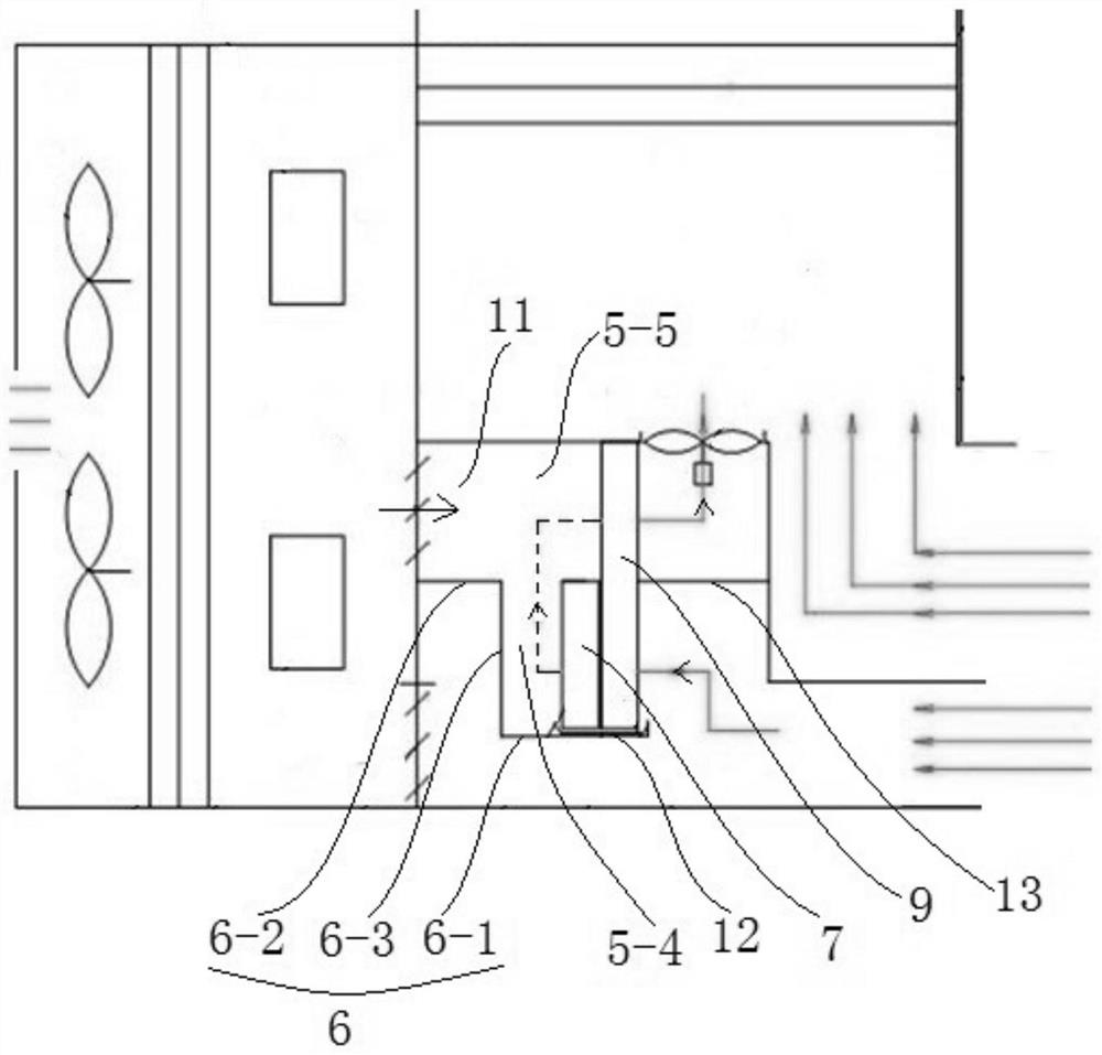
[0074] In order to make the objects, technical solutions and advantages of the present invention, the present invention will be further described in detail below with reference to the accompanying drawings and examples.

[0075] It should be noted that in the description of the present invention, the term "upper", "lower", "left", "right", "vertical", "horizontal", "inside", "outside", etc. The terminology of the relationship is based on the direction or positional relationship shown in the drawings, which is only for ease of description, rather than indicating or implying that the device or component must have a specific orientation, and therefore cannot be understood as a specific orientation. Limitations of the invention. Moreover, the term "first", "second" is for description purposes only, and cannot be understood as an indication or implies relative importance.

[0076] Further, it is also necessary to explain that in the description of the present invention, the term "mount...


PUM


Abstract

The invention discloses a drying equipment control method and a drying system. When the dry-bulb temperature in a curing barn is lower than a temperature threshold value and the wet-bulb temperature in the curing barn is lower than a low humidity threshold value, airflow in a main air duct is heated through a first condenser and a second condenser, the temperature in the curing barn is increased, and heat supply and temperature rise of the curing barn are achieved; when the dry-bulb temperature in the curing barn is lower than the temperature threshold value and the wet-bulb temperature in the curing barn is larger than or equal to the low-humidity threshold value, an inner dehumidification circulating fan operates, a dehumidification throttling device is turned on, air flow is dehumidified through the evaporation section of the heat pipe heat exchanger and the inner dehumidification evaporator, the air flow is heated through the condensation section of the heat pipe heat exchanger, a first condenser and a second condenser, so that the dry-bulb temperature and the wet-bulb temperature in the curing barn are increased; therefore, according to the drying equipment control method and the drying system, temperature and humidity control over the curing barn is achieved, heat recovery is conducted on air exhausted by the curing barn through the heat pipe heat exchanger, and the purposes of saving energy and reducing consumption are achieved.

Description

Technical field [0001] The present invention belongs to the field of drying, and is specifically, and is a drying device control method and a drying system. Background technique [0002] With the proposal of carbon-up, carbon neutralization and double carbon objectives, the country is increasingly attaching importance to the promotion of energy conservation and emission reduction. In response to the agricultural product processing industry, the air energy heat pump replaces the coal-fired roast house is gradually promoting national promotion, and is an important measures for national energy conservation and emission reduction. [0003] At present, the air energy heat pump tobacco drying equipment in the industry is usually based on the raw coalbed room. It is replaced by the radical boiler, and the air energy heat pump unit is used. The thermal energy is heated to the roasting house to heat the tobacco; where the baking room is usually borrowed from the original roast room struct...

Claims


Application Information

Patent Timeline
Patent Type & Authority Applications(China)
IPC IPC(8): A24B3/10
CPCA24B3/10Y02P70/50Y02P70/10
Inventor 杨公增王广杰
Owner QINGDAO HAIER AIR CONDITIONING ELECTRONICS CO LTD
Why Eureka
Try Eureka