Cold charging alloy pipe dismounting method

An alloy tube and cold-loading technology is applied in metal processing, metal processing equipment, manufacturing tools, etc., and can solve the problems of easy damage to the base material of the cold-loaded base 2, low disassembly efficiency, and difficulty in disassembling the cold-loaded alloy tube 1. To achieve the effect of easy realization of the dismantling method, good dismantling effect and low dismantling cost

Pending Publication Date: 2022-01-04
SHANGHAI ELECTRIC NUCLEAR POWER EQUIP CO LTD
View PDF8 Cites 0 Cited by
  • Summary
  • Abstract
  • Description
  • Claims
  • Application Information

AI Technical Summary

Problems solved by technology

However, due to the size interference fit between the cold-fitted alloy tube 1 and the cold-fitted base 2, it is very difficult to disassemble the cold-fitted alloy tube 1 by conventional disassembly methods without damaging the cold-fitted base 2. Not only is the disassembly efficiency low, but Moreover, it is easy to damage the base material of the cold-installed base 2, resulting in labor-hour consumption and economic loss

Method used


Image

  • Cold charging alloy pipe dismounting method
  • Cold charging alloy pipe dismounting method
  • Cold charging alloy pipe dismounting method

Examples


Embodiment 1

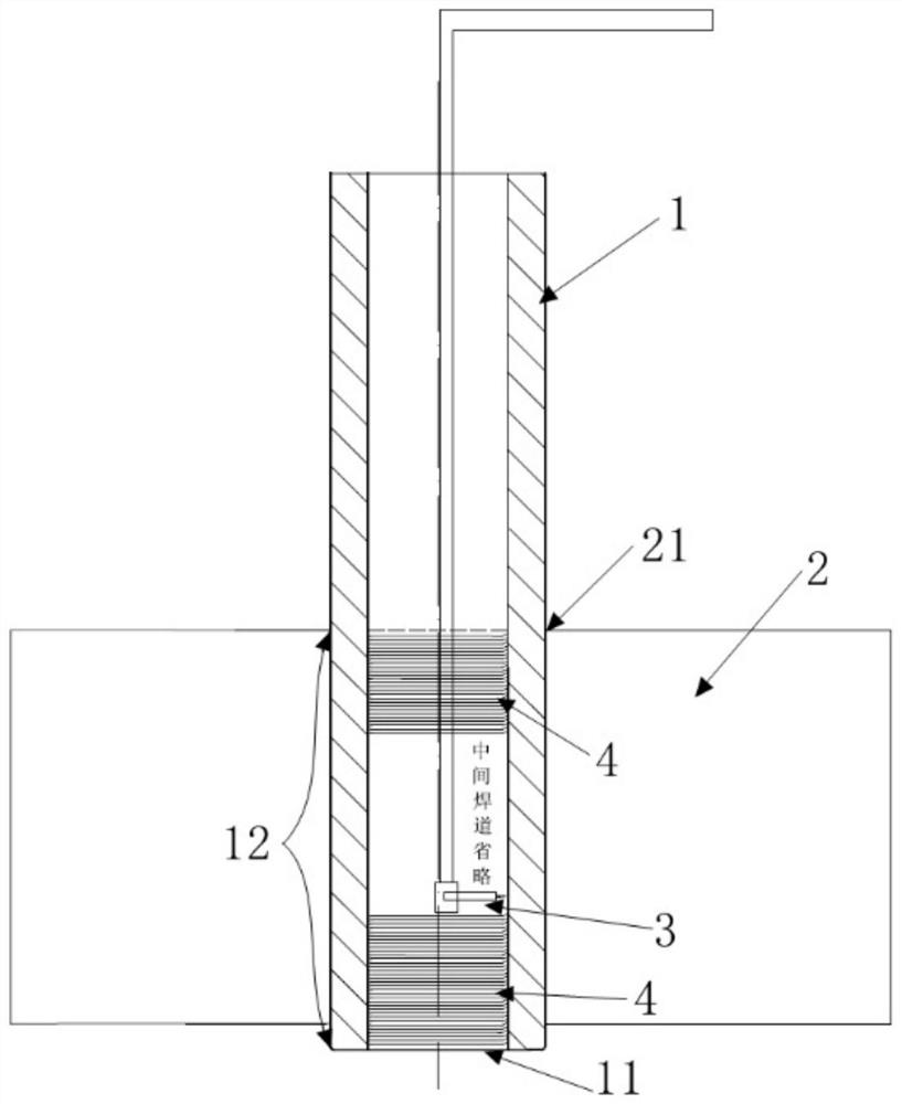
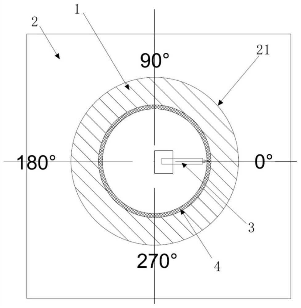
[0044] Circumferentially welded, as attached figure 2 , 3 As shown (attached figure 2 The middle bead is omitted), start arc welding from any position, perform single-layer or multi-layer welding in the counterclockwise or clockwise direction, each bead 4 is full circle or intermittent welding, and is carried out in continuous or intermittent welding state For the next welding (that is, 4 welds are spirally or spaced), the circumferential welding speed is 50mm-70mm / min. After the welding is completed, the inner wall of the welding operation section 12 is distributed in a single layer or evenly distributed in multiple layers along the axial direction. weld bead 4.

Embodiment 2

[0046] Axially welded, as attached Figure 4 , 5 As shown (attached Figure 4 The middle bead in the middle bead is omitted), start arc welding from any position, perform single-layer or multi-layer welding along the axial direction, and perform the next welding in the continuous / stop welding state (that is, weld bead 4 helical or spaced distribution), the axis The welding speed in the direction is 70mm-80mm / min. After the welding is completed, the inner wall of the welding operation section 12 is distributed in a single layer or in multiple layers in the circumferential direction with weld beads 4 parallel to the axis.

[0047] 4. During the welding process, monitor the temperature of the tube wall of the alloy tube 1 and the cold loading base 2. If the temperature of the inner wall of the cold loading hole 21 is too high or the temperature difference is too large, it may cause thermal deformation of the base metal of the cold loading base 2 and cause When damaged, stop wel...


PUM


Abstract

The invention provides a cold charging alloy pipe dismounting method. The method is used for dismounting an alloy pipe of a cold charging test piece from a cold charging hole of a cold charging base through a welding heating method. The cold charging alloy pipe dismounting method comprises the steps that S1, inner wall base metal of a welding operation section is heated in an alloy pipe through a welding method, so that the inner wall base metal of the welding operation section of the alloy pipe is locally melted; S2, welding is stopped after welding operation of the welding operation section is completed, locally-molten base metal on the inner wall of the welding operation section of the alloy pipe is solidified and shrunk, the outer diameter of the outer wall of the alloy pipe is correspondingly reduced, and clearance fit is formed between the alloy pipe and the cold charging hole; and S3, the alloy pipe is separated from the cold charging base through external force such as gravity or hoisting force, and dismounting is completed. According to the cold charging alloy pipe dismounting method provided by the invention, the cold charging alloy pipe can be conveniently and efficiently dismounted, a cold charging base body is not damaged, and the method has the advantages of being stable in process, high in dismounting efficiency, low in dismounting cost, capable of saving manpower and the like, and has good practicability and economic value.

Description

technical field [0001] The invention relates to the technical field of nuclear power equipment, in particular to a method for removing cold-packed alloy pipes. Background technique [0002] The evaporator, voltage stabilizer and other nuclear island main equipment of the nuclear power plant, due to the technical requirements of technical parameters, assembly accuracy, etc., usually need to cold install the nickel-based alloy tubes, alloy steel tubes and other alloy tubes in the equipment. Alloy pipe cold installation method as attached figure 1 As shown, the outer diameter of the alloy pipe 1 is D1, and the side of the alloy pipe 1 ready for cold fitting is the cold fitting end 11; the cold fitting base 2 is provided with a cold fitting hole 21, and the inner diameter of the cold fitting hole 21 is D2 , D1>D2 and there is an assembly interference of 0.04-0.06mm; before cold-fitting, immerse the side of the cold-fitting end 11 of the alloy tube 1 in liquid nitrogen for 15-20...

Claims


Application Information

Patent Timeline
Patent Type & Authority Applications(China)
IPC IPC(8): B23P11/00
CPCB23P11/025
Inventor 侯冬冬江才林张茂龙张敏苏平吕映宾罗庆朱志华
Owner SHANGHAI ELECTRIC NUCLEAR POWER EQUIP CO LTD
Why Eureka
Try Eureka