Method for achieving geothermal power generation through double-working-medium underground heat exchange and heat exchange production structure

A geothermal power generation and duplex technology, which is applied in geothermal power generation, heat collectors using groundwater as the working fluid, earthwork drilling and mining, etc., can solve problems affecting the power generation efficiency and heat dissipation of duplex geothermal power stations, Achieve the effects of improving thermoelectric conversion efficiency, less energy dissipation, and improving cycle heat extraction efficiency

Pending Publication Date: 2022-01-04
BC P INC CHINA NAT PETROLEUM CORP +1
View PDF3 Cites 1 Cited by
  • Summary
  • Abstract
  • Description
  • Claims
  • Application Information

AI Technical Summary

Problems solved by technology

[0005] However, in this technology, the production process of the high-temperature formation fluid from the bottom of the well to the surface will continue to exchange heat with the formation or the pipe string, and the fluid will dissipate a large amount of heat during the flow of the thousands of meters of the pipe string, seriously affecting the Power generation efficiency of duplex geothermal power station

Method used


Image

  • Method for achieving geothermal power generation through double-working-medium underground heat exchange and heat exchange production structure
  • Method for achieving geothermal power generation through double-working-medium underground heat exchange and heat exchange production structure

Examples


Embodiment Construction

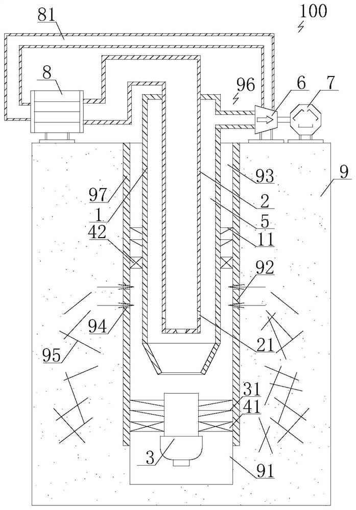
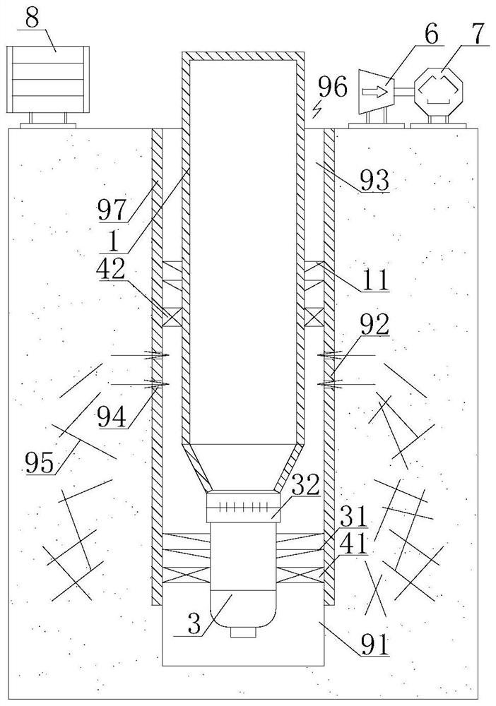
[0044] In order to have a clearer understanding of the technical features, purposes and effects of the present invention, the specific implementation manners of the present invention will now be described with reference to the accompanying drawings.

[0045]The specific implementations of the present invention described here are only for the purpose of explaining the present invention, and should not be construed as limiting the present invention in any way. Under the teaching of the present invention, the skilled person can conceive any possible modification based on the present invention, and these should be regarded as belonging to the scope of the present invention. It should be noted that when an element is referred to as being “disposed on” another element, it may be directly on the other element or there may also be an intervening element. When an element is referred to as being "connected to" another element, it can be directly connected to the other element or interve...


PUM


Abstract

The invention discloses a method for achieving geothermal power generation through double-working-medium underground heat exchange and a heat exchange production structure. The method comprises the following steps that an open hole section, a perforation section and a well section annulus are formed in a well from bottom to top; an electric submersible pump and a first packer are put into a geothermal production well through a production pipe column, and the open hole section and the perforation section are sealed and separated through the first packer in a setting mode; the production pipe column is separated from the electric submersible pump, and a second packer on the production pipe column sets and packs the perforation section and the well section annulus; a heat removal working medium injection pipe column is put down into the production pipe column, and high-pressure gas is injected into the annulus of the pipe column to replace accumulated liquid in the pipe column in a reverse circulation mode; the electric submersible pump is started to circulate geothermal fluid of a stratum, meanwhile, a liquid heat removal working medium, a gaseous heat removal working medium and the geothermal fluid are injected into the heat removal working medium injection pipe column to complete double-working-medium heat exchange at the well bottom, heat energy of the geothermal fluid is converted into heat removal working medium pressure energy, and the gaseous heat removal working medium is output from a well opening; and when the wellhead stably generates the gaseous heat removal working medium, the wellhead is switched to a turbine to drive a generator set to generate power.

Description

technical field [0001] The invention relates to the technical field of geothermal resource development, in particular to a process method for duplex heat exchange underground to realize power generation using medium-high temperature geothermal resources, that is, a method for duplex underground heat exchange to realize geothermal power generation and a heat exchange production structure. Background technique [0002] my country has huge reserves of geothermal resources, and geothermal resources are a kind of clean and renewable energy with important application value and development potential. With the continuous improvement of the requirements for reducing the use of fossil energy and reducing greenhouse gas emissions, and the continuous advancement of the carbon peak action plan and carbon neutral long-term planning, the development potential of clean and renewable energy such as geothermal energy, solar energy, and wind energy has been deeply tapped. It has become an inevi...

Claims


Application Information

Patent Timeline
Patent Type & Authority Applications(China)
IPC IPC(8): E21B43/00E21B43/11E21B41/00E21B33/122F24T10/20
CPCE21B43/121F24T10/20E21B33/122E21B43/11E21B41/00Y02E10/10
Inventor 张宏源查永进卓鲁斌于璟周翠平李冰张佳伟方朝合
Owner BC P INC CHINA NAT PETROLEUM CORP
Why Eureka
Try Eureka