Supercharge Your Innovation With Domain-Expert AI Agents!

Circuit measuring system for substrate

A circuit and substrate technology, applied in the field of substrate circuit measurement system, can solve problems such as slow measurement time, unsatisfactory electrical performance, inaccurate line width measurement, etc., to improve accuracy and increase detection accuracy , the effect of increasing the accuracy

Pending Publication Date: 2022-01-04
UTECHZONE CO LTD
View PDF0 Cites 1 Cited by
  • Summary
  • Abstract
  • Description
  • Claims
  • Application Information

AI Technical Summary

Problems solved by technology

[0005] With the increasing frequency of circuit signals and the trend of thinner circuit board lines, the cross-sectional area consistency of circuit board lines is more critical to the image of circuit characteristics such as resistance and impedance. Slight changes will lead to poor performance of final electrical appliances expected
[0006] The circuit inspection of traditional circuit boards mostly uses black and white cameras and diffuse light sources, which will make it difficult to identify the upper and lower lines of the circuit, especially when the edge of the upper line has a curved corner. Inaccurate, and incorrect calculation of line cross-sectional area
[0007] On the other hand, in the traditional 3D inspection of lines, Confocal microscopy, triangular reflection technology, white light interference technology, etc. are mainly used to establish 3D models by point measurement. Not only the measurement time Too slow, it is difficult to carry out a large number of inspections, due to the limitation of point measurement, only local height information can be obtained, and it is difficult to combine into complete line cross-sectional area information

Method used


Image

  • Circuit measuring system for substrate
  • Circuit measuring system for substrate
  • Circuit measuring system for substrate

Examples


Embodiment Construction

[0112] The embodiments described below by referring to the figures are exemplary only for explaining the present invention and should not be construed as limiting the present invention.

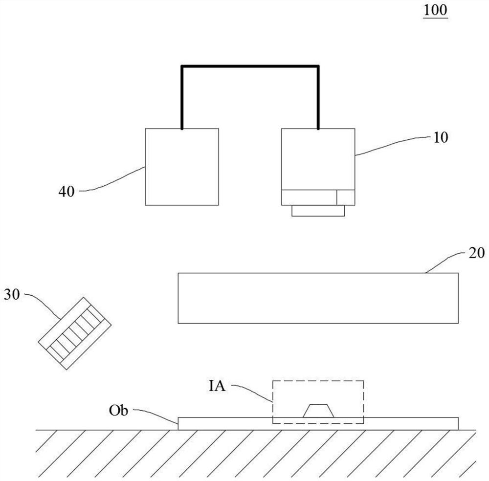
[0113] Please refer to " figure 1 " is a schematic block diagram of the line measurement system of the present invention. The line measurement system 100 of this embodiment mainly includes an image capture device 10 , a first light source 20 , a second light source 30 and an image processing device 40 .

[0114] The image capture device 10 is used to capture the image of the substrate Ob to obtain an image of the substrate. The image capture device 10 includes but is not limited to, for example, a color camera for photographing the substrate Ob on the inspection area IA. Wherein the substrate Ob includes at least one substrate circuit. In one embodiment, the image capture device 10 may be an area scan camera or a line scan camera.

[0115] The first light source 20 provides light beams of ...


PUM


Abstract

The invention discloses a circuit measuring system for a substrate. The circuit measuring system comprises a first light source, a second light source, image capturing equipment and an image processing device. The first light source provides a first color light beam to a substrate to display a first region feature of the substrate. The second light source provides a second color light beam to the substrate so as to display a second area characteristic of the substrate. The image capturing equipment captures an image of the substrate to obtain the first region feature and the second region feature. The image processing device is connected to the image capturing device and analyzes the first region feature and the second region feature to obtain line information. According to the invention, the image contrast among a plurality of feature areas on the line can be effectively increased, so that the accuracy of line measurement can be improved, and the accuracy of detection is further improved.

Description

technical field [0001] The invention relates to a circuit measurement system, in particular to a circuit measurement system for a substrate which improves the contrast ratio of a circuit through a multi-color light source. Background technique [0002] With the progress of the fully automated industry, Automatic Optical Inspection (AOI) has been widely used in the visual inspection of circuit board assembly production lines in the electronics industry and has replaced the previous manual visual inspection (Visual Inspection). [0003] The automatic optical identification system is a common representative method in the industrial process. The main method is to use the camera device to take pictures of the surface state of the object to be tested, and then use computer image processing technology to detect defects such as foreign objects or abnormal patterns. Due to the use of non-contact Formal inspection, so it can be used to inspect semi-finished products during the product...

Claims


Application Information

Patent Timeline
IPC IPC(8): G01N21/956G01B11/02G01B11/06G01B11/28G01B11/00
CPCG01N21/95607G01B11/02G01B11/06G01B11/28G01B11/00G01N2021/95638G01N21/956G01N21/8806G01N21/8851G01R31/28G06T7/0004G01N2021/8816G01N2021/8887
Inventor 邹嘉骏林伯聪黄冠勋张勋豪
Owner UTECHZONE CO LTD
Features
  • R&D
  • Intellectual Property
  • Life Sciences
  • Materials
  • Tech Scout
  • Unparalleled Data Quality
  • Higher Quality Content
  • 60% Fewer Hallucinations
Learn More