
Ejecting mounting mechanism for assembling missiles under belly of airplane and control method of ejecting mounting mechanism

A missile and top-mounted technology, applied in two-dimensional position/course control, aircraft parts, non-electric variable control, etc., can solve the problems of complex operation of equipment, interference of power supply lines, low work efficiency, etc., and achieve high transmission efficiency, Responsive, well-structured effects

Pending Publication Date: 2022-01-07
NORTHEAST FORESTRY UNIVERSITY
View PDF6 Cites 1 Cited by
  • Summary
  • Abstract
  • Description
  • Claims
  • Application Information

AI Technical Summary

Problems solved by technology

[0003] In order to solve the technical problems of power supply line interference, time-consuming and labor-intensive, low work efficiency, complicated equipment operation and other technical problems in the prior art aircraft belly-mounted equipment mentioned in the above-mentioned background technology, the present invention proposes a missile assembly for aircraft belly The top-loading mechanism and its control method can realize the rapid assembly of missiles of various sizes under the belly of the aircraft. The mechanism is easy to operate, reasonable in structure, accurate in positioning, fast in response, and has high versatility and stability.

Method used


Image

  • Ejecting mounting mechanism for assembling missiles under belly of airplane and control method of ejecting mounting mechanism
  • Ejecting mounting mechanism for assembling missiles under belly of airplane and control method of ejecting mounting mechanism
  • Ejecting mounting mechanism for assembling missiles under belly of airplane and control method of ejecting mounting mechanism

Examples


specific Embodiment approach 1

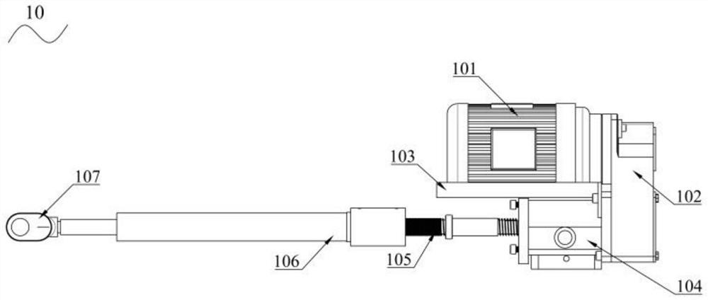
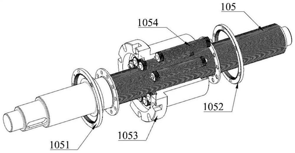
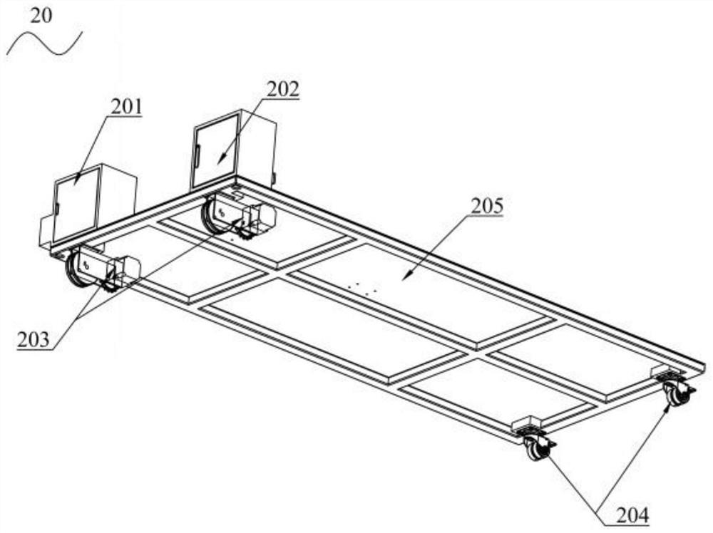
[0036] Specific implementation mode one: see Figure 1-8This embodiment will be described. The top loading mechanism for missile assembly under the belly of the aircraft described in this embodiment includes a power transmission mechanism 10 based on a planetary roller screw, a travel control mechanism 20, an upper platform support mechanism 30, a scissor lift mechanism 40 and a base 205, the upper end of the scissor lift mechanism 40 is connected to the upper platform support mechanism 30, and the bottom is installed on the slideway of the base 205, the travel control mechanism 20 remotely controls the base 205 to advance to the designated station, and the power transmission mechanism 10 controls the scissors Type elevating mechanism 40 rises or descends to missile installation height.

[0037] The power transmission mechanism based on the planetary roller screw includes a screw drive motor 101, a screw drive motor reducer 102, a planetary roller screw lever 105 and a screw ...


PUM


Abstract

The invention discloses an ejecting mounting mechanism for assembling missiles under the belly of an airplane and a control method of the ejecting mounting mechanism. The ejecting mounting mechanism comprises a power transmission mechanism, a walking control mechanism, a shear fork type lifting mechanism and an upper platform supporting mechanism, the power transmission mechanism is installed on a base through a positioning bolt and connected with a cross beam on the rear portion of the shear fork type lifting mechanism through a connecting fork head, an ejecting mounting machine walking driving mechanism adopts a motor to drive a driving wheel, and an ejecting mounting mechanism is controlled by a remote controller to reach a specified station in a working area according to requirements. According to the ejecting mounting mechanism, a full-electric control mode is adopted, and walking of the ejecting mounting mechanism and positioning adjustment of the lifting mechanism and the upper platform mechanism are achieved in a wireless remote control mode; and according to the ejecting mounting mechanism, rapid assembly of missiles of various sizes and models under the belly of the airplane can be realized, and the mechanism is convenient to operate, reasonable in structure, accurate in positioning and high in response speed, and has relatively high universality and stability.

Description

technical field [0001] The invention relates to a top-loading mechanism for assembling missiles under the belly of an aircraft and a control method thereof, belonging to the technical field of assembling missiles mounted on aircraft. Background technique [0002] With the continuous development of modern warfare, higher requirements are put forward for the convenience, timeliness and safety of military aircraft missile assembly. The workplaces for missile assembly are mainly concentrated in the belly of the aircraft. Top-loading technology and equipment have made considerable progress in my country in recent years. Domestically-made top-mounted vehicles have developed particularly rapidly. Many different models and forms of top-loaded vehicles have appeared on the market. The current aircraft belly-mounted The equipment can mainly include three forms of manual direct mounting, hanging equipment mounting and lifting equipment mounting. There are problems such as power supply l...

Claims


Application Information

Patent Timeline
Patent Type & Authority Applications(China)
IPC IPC(8): B23P19/00G05D1/02
CPCB23P19/00G05D1/0276B23P2700/01
Inventor 解志杰张庆博吕景亮倪佳楠刘九庆
Owner NORTHEAST FORESTRY UNIVERSITY
Learn More