
Laser device

A technology of laser devices and laser media, applied in lasers, laser parts, laser parts, etc., can solve problems such as reduced processing quality and beam distribution damage

Pending Publication Date: 2022-01-07
SUMITOMO HEAVY IND LTD
View PDF2 Cites 0 Cited by
  • Summary
  • Abstract
  • Description
  • Claims
  • Application Information

AI Technical Summary

Problems solved by technology

If the incident position on the beam shaping optical system deviates, the beam distribution on the processing surface will be destroyed, resulting in a decrease in processing quality

Method used


Image

  • Laser device
  • Laser device
  • Laser device

Examples


Embodiment Construction

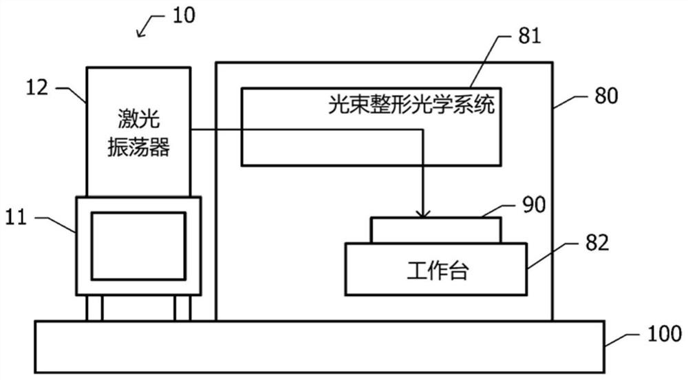
[0022] Below, refer to Figures 1 to 7B , the laser device based on the embodiment will be described.

[0023] figure 1 It is a schematic diagram of a laser device 10 according to an embodiment and a processing device 80 for processing using a laser beam output from the laser device 10 . The laser device 10 and the processing device 80 are fixed on a common base 100 . The common base 100 is, for example, the ground.

[0024] The laser device 10 includes a stand 11 fixed on a common base 100 and a laser oscillator 12 supported on the stand 11 . The processing device 80 includes a beam shaping optical system 81 and a workbench 82 . The object to be processed 90 is held on the table 82 . The beam shaping optical system 81 and the workbench 82 are fixed on the common base 100 . The beam profile of the laser beam output from the laser oscillator 12 is shaped by the beam shaping optical system 81 and is incident on the object 90 to be processed.

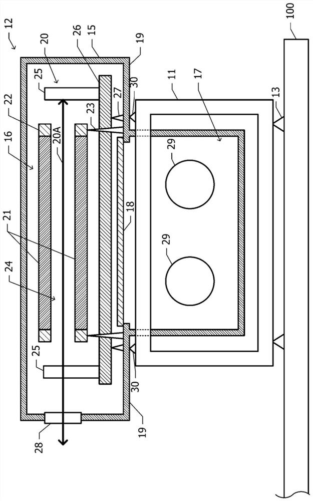
[0025] figure 2 is a side ...


PUM


Abstract

The invention provides a laser device which does not easily to deviate even if a chamber is thermally deformed. The chamber accommodates a laser medium gas and an optical resonant cavity. A gantry supports the chamber. The position of the chamber in the horizontal direction with respect to the gantry is restricted in one location. The chamber is supported so as to be movable in the horizontal direction with respect to the stage, except for a portion where the position of the chamber in the horizontal direction with respect to the stage is restricted.

Description

[0001] This application claims priority based on Japanese Patent Application No. 2020-116378 filed on July 6, 2020. The entire content of this Japanese application is incorporated in this specification by reference. technical field [0002] The invention relates to a laser device. Background technique [0003] The chamber of the gas laser oscillator is supported on a stand. In this configuration, the chamber is typically secured to the gantry using four locations. In the three-axis orthogonal type laser oscillator, the laser medium gas in the chamber is circulated at high speed in order to stabilize the discharge of the discharge electrode. The laser dielectric gas flows into the discharge region between the pair of discharge electrodes, and the laser dielectric gas that has become high temperature due to the discharge is discharged from the discharge region to other regions in the chamber. The laser medium gas discharged from the discharge area is cooled by the heat exch...

Claims


Application Information

Patent Timeline
IPC IPC(8): H01S3/03H01S3/081
CPCH01S3/03H01S3/081H01S3/027H01S3/08
Inventor 河村让一田中研太
Owner SUMITOMO HEAVY IND LTD
Learn More