
Annular blowing, drying and dehumidifying device and method applied to cold and hot stage and application

A technology of drying and dehumidification, hot and cold table, applied in the field of atmospheric science, can solve the problems of high price, low cost-effectiveness and high noise of dehumidifiers, and achieve the effect of good drying and dehumidification effect, simple and compact structure and long service life.

Active Publication Date: 2022-01-11
PEKING UNIV
View PDF9 Cites 0 Cited by
  • Summary
  • Abstract
  • Description
  • Claims
  • Application Information

AI Technical Summary

Problems solved by technology

However, industrial-grade rotary dehumidifiers are expensive, occupy a large area, have high power, strong vibration, and high noise. They require a certain degree of indoor renovation, and the cost of manpower, time, and money is relatively high; while most indoor research laboratories have Ventilation requirements, faster air circulation, put forward higher requirements on the dehumidification capacity of the dehumidifier
[0007] To sum up, the existing method of using a dehumidifier to reduce the relative humidity of the indoor air, thereby preventing the sample observation window of the cold and hot table from fogging due to condensation of air moisture during the cooling process, has poor effect, high cost, and large floor space. , high noise, low cost-efficiency ratio, and other defects, it is difficult to meet the needs of cold and hot station research in the new era
[0008] Through the search, no patent publications related to the patent application of the present invention have been found

Method used


Image

  • Annular blowing, drying and dehumidifying device and method applied to cold and hot stage and application
  • Annular blowing, drying and dehumidifying device and method applied to cold and hot stage and application
  • Annular blowing, drying and dehumidifying device and method applied to cold and hot stage and application

Examples


Embodiment Construction

[0059] The present invention will be described in further detail below in conjunction with specific examples. The following examples are only descriptive, not restrictive, and cannot limit the protection scope of the present invention.

[0060] Structures not described in detail in the present invention can be understood as conventional structures in the art.

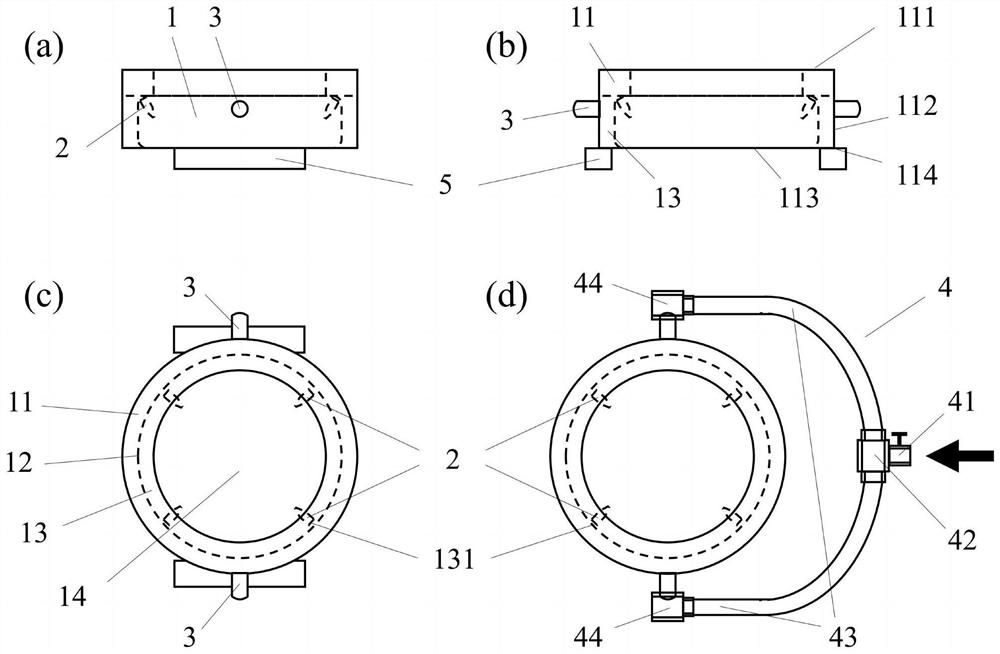
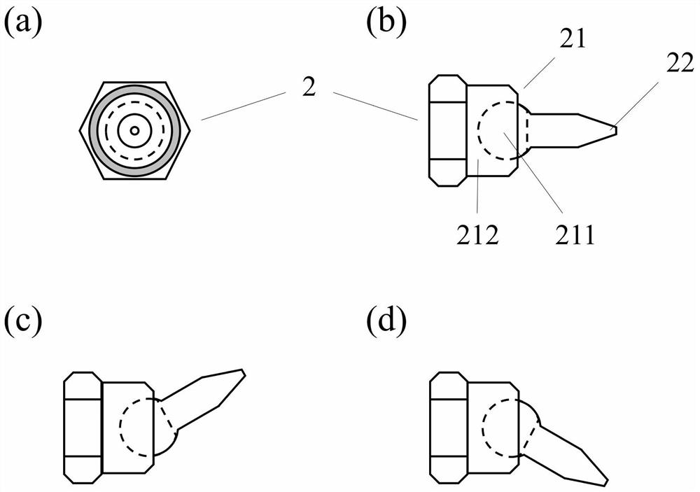
[0061] A ring-shaped purge drying and dehumidification device applied to cold and hot platforms, such as Figure 1 to Figure 3 As shown, the device includes an annular purger 1, a rotary adjustable nozzle 2, an air inlet 3, an air path distributor 4, and a fixed connecting frame 5, and the annular purging device 1 can be connected to the The device for purging, drying and dehumidification (not shown in the figure, which can be such as a hot and cold platform) is detachably connected and arranged, and the rotary adjustable nozzle 2 is evenly arranged on the annular purger 1 at intervals along the circumferential directio...


PUM


Abstract

The invention discloses an annular blowing, drying and dehumidifying device applied to a cold and hot stage. The device comprises an annular blowing device (1), rotary adjusting spray heads (2), an air inlet (3), an air channel distributor (4) and a fixed connecting frame (5), wherein the annular blowing device (1) can be detachably connected with a device to be blown, dried and dehumidified through the fixed connecting frame (5); and the rotary adjusting spray heads (2) are uniformly distributed on the annular blowing device (1) at intervals in the circumferential direction, and the rotary adjusting spray heads (2) can spray a blowing medium to blow a part to be blown, dried and dehumidified of the device. The device disclosed by the invention can be used for stably and uniformly spraying dry purge gas to a sample observation window of the whole cold and hot stage at a high speed, isolating indoor humid ambient air and preventing the sample observation window from fogging to influence the experiment of the cold and hot stage; and the device has the advantages of high efficiency, flexibility and low cost, and is suitable for various types and specifications of cold and hot stages and related instruments.

Description

technical field [0001] The invention belongs to the technical field of atmospheric science, in particular to an annular purge drying and dehumidification device, method and application applied to cold and hot stations. Background technique [0002] The cold and hot stage is a scientific research equipment widely used in professional fields such as geology, atmospheric science, material science, food science, and pharmacology. It can be used with optical microscopes, scanning electron microscopes, environmental scanning electron The combination of focusing Raman microscope, fluorescence microscope and other microscope equipment can be used in mineral inclusion testing, atmospheric ice nuclei determination, polymer material phase transition and morphological change, food freeze-drying preservation, drug freeze-drying structure analysis, etc. The equipment precisely controls the temperature of the platform through programming, rapidly heats or cools the sample, and observes and...

Claims


Application Information

Patent Timeline
IPC IPC(8): F26B21/00F26B21/12F26B21/14F25D31/00G01N21/01
CPCF26B21/004F26B21/12F26B21/14F25D31/005G01N21/01G01N2021/0112
Inventor 吴志军陈景川
Owner PEKING UNIV
Learn More