
Welding chopper and welding equipment

A hacking knife and transition connection technology, which is applied in the field of semiconductor packaging, can solve problems such as energy accumulation, line tail breakage, product quality hazards, etc., and achieve the effects of efficient energy transmission, reducing the number of alarms, and reducing wear and tear

Pending Publication Date: 2022-01-14
苏州三环科技有限公司 +1
View PDF0 Cites 0 Cited by
  • Summary
  • Abstract
  • Description
  • Claims
  • Application Information

AI Technical Summary

Problems solved by technology

[0005] 1. The inner chamfer between the inner hole and the outer arc is likely to increase the concentration of the solder ball stress and energy accumulation, resulting in serious aluminum extrusion and easy damage to the silicon material under the aluminum layer, resulting in craters on the chip pad
[0006] 2. When welding the second solder joint, stress concentration is prone to occur, resulting in the tail of the wire not being effectively connected to the carrier, and the tail of the wire breaks during the rising process of the chopper, causing the machine to alarm for short wire tails, resulting in hidden dangers to product quality

Method used


Image

  • Welding chopper and welding equipment
  • Welding chopper and welding equipment

Examples


Embodiment Construction

[0023] This part will describe the specific embodiment of the present invention in detail, and the preferred embodiment of the present invention is shown in the accompanying drawings. Each technical feature and overall technical solution of the invention, but it should not be understood as a limitation on the protection scope of the present invention.

[0024] In the present invention, "several" means one or more, "multiple" means more than two, "greater than", "less than", "exceeding", etc. are understood as excluding the original number; "above", "below", "within" " and so on are understood as including the original number. In the description of the present invention, if "first" and "second" are used only for the purpose of distinguishing technical features, it should not be understood as indicating or implying relative importance or implicitly indicating the number of indicated technical features or Implicitly indicates the sequence of the indicated technical features.

...


PUM

PropertyMeasurementUnit
radiusaaaaaaaaaa
radiusaaaaaaaaaa
radiusaaaaaaaaaa

Abstract

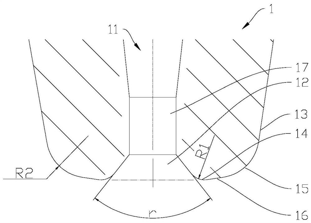
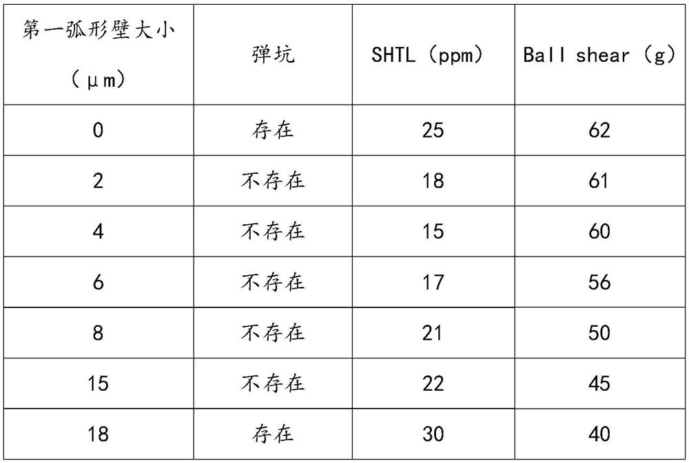
The invention discloses a welding chopper and welding equipment. The welding chopper is provided with a wire passing through hole, the wire passing through hole extends to the end of the welding chopper, the position, close to the end of the welding chopper, of the wire passing through hole is provided with a conical inner wall surface expanding outwards, and the conical inner wall surface is connected with the outer wall surface of the welding chopper through arc-shaped wall surfaces; the arc-shaped wall surfaces comprise a first arc-shaped wall surface and a second arc-shaped wall surface, the first arc-shaped wall surface is closer to the end of the welding chopper relative to the second arc-shaped wall surface, the first arc-shaped wall surface is in transition connection with the outer wall surface of the welding chopper through the second arc-shaped wall surface, and the second arc-shaped wall surface is in transition connection with the conical inner wall surface through the first arc-shaped wall surface; and the radius of the first arc-shaped wall surface is R1, and R1 is larger than 0 and smaller than or equal to 15 micrometers. According to the welding chopper and the welding equipment, the concentration ratio, to the stress of a welding ball, of the welding chopper can be reduced, craters, caused by stress concentration, of a chip bonding pad are reduced, the concentration of tangent line tail force when a second welding spot is welded is reduced, and the occurrence of line tail breakage in the rising process of the chopper is reduced.

Description

technical field [0001] The invention is used in the technical field of semiconductor packaging, and in particular relates to a welding chopper and welding equipment. Background technique [0002] In the production process of semiconductor integrated circuits, it is usually necessary to connect the soldering area of ​​the semiconductor bare chip with the I / 0 lead of the microelectronic package or the metal wiring welding area on the substrate with a metal filament (welding wire). [0003] Generally, the welding wire is passed through the wire hole of the chopper, and the welding wire is welded by thermocompression bonding or ultrasonic bonding (that is, under the action of heating, pressure or friction, the welding wire and the welding area The atoms on the contact surface reach the range of atomic attraction and are welded). Specifically, the welding wire is bonded with the first welding station to form a first bonding point (that is, one end of the welding wire has been fi...

Claims


Application Information

Patent Timeline
Patent Type & Authority Applications(China)
IPC IPC(8): B21F11/00
CPCB21F11/00
Inventor 邱基华陈烁烁
Owner 苏州三环科技有限公司
Learn More