Photovoltaic cell horizontal electroplating equipment and method

A photovoltaic cell and electroplating equipment technology, applied in plating tanks, electrolytic components, electrolytic processes, etc., can solve problems such as long product size and poor quality of photovoltaic cell coating, to increase uniformity, improve electroplating efficiency, and avoid rough edges problem effect

Pending Publication Date: 2022-01-14
ZHEJIANG AIKO SOLAR ENERGY TECH CO LTD +3
View PDF0 Cites 9 Cited by
  • Summary
  • Abstract
  • Description
  • Claims
  • Application Information

AI Technical Summary

Problems solved by technology

[0004] The invention provides a horizontal electroplating equipment for photovoltaic cells, which aims to solve the problems that the horizontal electroplating equipment for photovoltaic cells in the prior art has a long product size and poor quality of coatings for photovoltaic cells

Method used


Image

  • Photovoltaic cell horizontal electroplating equipment and method
  • Photovoltaic cell horizontal electroplating equipment and method
  • Photovoltaic cell horizontal electroplating equipment and method

Examples


Embodiment 1

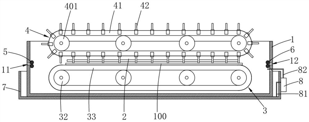
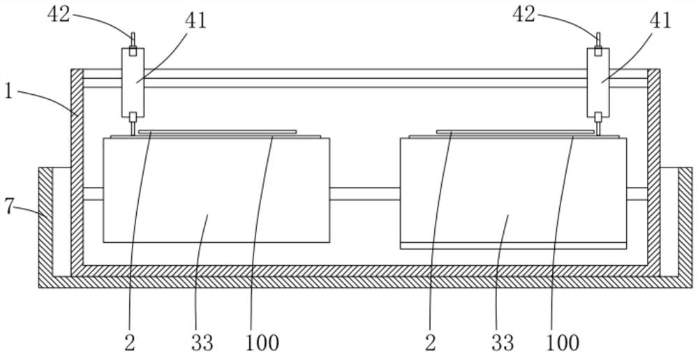
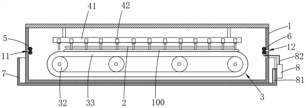
[0035] Please refer to Figure 1-Figure 2 , an embodiment of the present invention provides a horizontal electroplating equipment for photovoltaic cells, including:

[0036] An electroplating tank 1, the electroplating tank 1 is equipped with an electroplating solution, one end of the electroplating tank 1 is provided with an inlet 11, and the other end of the electroplating tank 1 is provided with an outlet 12 opposite to the inlet 11;

[0037] An anode part 2 arranged in the electroplating tank 1 and located below the liquid level of the electroplating solution;

[0038] The cell moving mechanism 3 provided in the electroplating tank 1 is used to drive the cell 100 to move from the entrance 11 to the exit 12, so that the cell 100 moves relative to the anode part 2 in the electroplating solution to realize electroplating;

[0039] The cathode conductive assembly 4 arranged in the electroplating tank 1 includes a rotary motion part 41 driven by a driving device, and a plurali...

Embodiment 2

[0081] The embodiment of the present invention also provides a method for electroplating photovoltaic cells using the photovoltaic cell horizontal electroplating equipment of the first embodiment, the method includes the following steps:

[0082] a. The cell moving mechanism 3 drives the cell 100 to move from the inlet 11 to the outlet 12, so that the cell 100 enters the electroplating tank 1 and moves relative to the anode 2 in the electroplating solution;

[0083] In this step, the battery piece moving mechanism 3 drives the battery piece 100 of the battery piece 100 to enter the electroplating tank 1 from the inlet 11, and the battery piece moving mechanism 3 continues to drive the battery piece 100 to move the battery from the inlet 11 to the outlet 12. piece 100, so that the battery piece 100 moves relative to the anode part 2 in the electroplating solution, and at the same time cooperates with the rotating movement part 41 to drive a plurality of cathode conductive probes...


PUM


Abstract

The invention is applicable in the technical field of photovoltaic cell electroplating, and provides photovoltaic cell horizontal electroplating equipment and method. The photovoltaic cell horizontal electroplating equipment comprises an electroplating bath which is filled with electroplating liquid and is provided with an inlet and an outlet opposite to the inlet, an anode piece which is arranged in the electroplating bath and is located below the liquid level of the electroplating liquid, a cell moving mechanism which is used for driving a cell to move from the inlet to the outlet so as to enable the cell to move relative to the anode piece in the electroplating liquid to realize electroplating, and a cathode conductive assembly; the cathode conductive assembly comprises a rotary moving piece and a plurality of cathode conductive probes arranged on the rotary moving piece, and the rotary moving piece can drive the plurality of cathode conductive probes to synchronously rotate, so that at least one cathode conductive probe makes contact with the cell and keeps synchronous movement with the cell. According to the photovoltaic cell horizontal electroplating equipment, the coating quality of the photovoltaic cell can be effectively improved, and the overall length size of the photovoltaic cell horizontal electroplating equipment can be greatly reduced.

Description

technical field [0001] The invention relates to the technical field of photovoltaic cell electroplating, in particular to a photovoltaic cell horizontal electroplating equipment and method. Background technique [0002] With the continuous expansion of the scale of the photovoltaic industry and the rapid development of the market, as well as the adjustment of relevant policies, the market has increasingly strict requirements on the price of photovoltaic cells, resulting in the reduction of complexity in many processes and the use of materials that are easy to obtain. Existing solar cells usually use silver paste printed on the cells, and the silver paste accounts for more than 25% of the total cost of producing solar cells, so how to replace the silver paste is a key point. At present, many companies use electroplating copper to replace printed silver paste. The basic principle is to let the cells pass through the cathode assembly and the anode assembly in turn, and use elec...

Claims


Application Information

Patent Timeline
Patent Type & Authority Applications(China)
IPC IPC(8): C25D17/00C25D17/02C25D21/12
CPCC25D17/02C25D21/12C25D17/001
Inventor 朱玮陈刚
Owner ZHEJIANG AIKO SOLAR ENERGY TECH CO LTD
Why Eureka
Try Eureka