Directional variable flow type hydraulic fracturing system and method

A splitting and hydraulic technology, applied in the field of directional variable flow hydraulic splitting systems, can solve the problems of inability to automatically and accurately control the splitting point and splitting timing and the high splitting pressure, experience and technical requirements, and achieve fixed The effect of stability, high security and low error rate

Pending Publication Date: 2022-01-14
GUANGXI NEWHARBOR ENG CO LTD
View PDF0 Cites 0 Cited by
  • Summary
  • Abstract
  • Description
  • Claims
  • Application Information

AI Technical Summary

Problems solved by technology

[0006] The purpose of the present invention is to provide a directional variable flow hydraulic splitting system and method, so as to overcome the inability of the existing hydraulic splitting device and method to automatically and accurately control the splitting timing and splitting pressure of the splitting point. Defects with high artificial experience and technical requirements

Method used


Image

  • Directional variable flow type hydraulic fracturing system and method
  • Directional variable flow type hydraulic fracturing system and method
  • Directional variable flow type hydraulic fracturing system and method

Examples


Embodiment 1

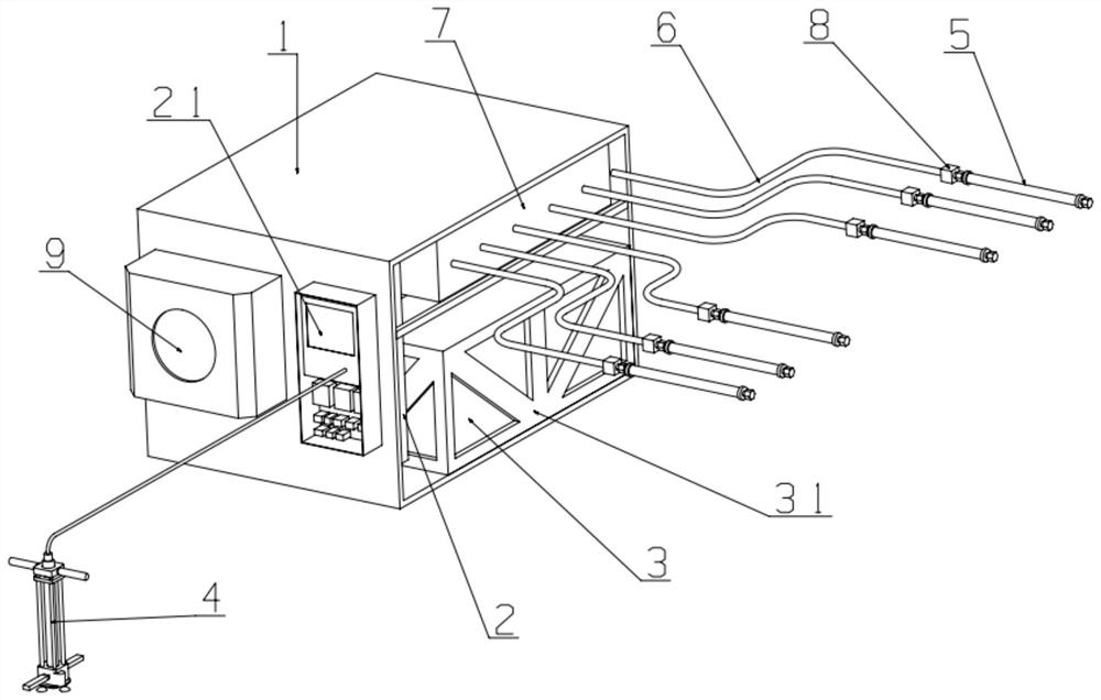
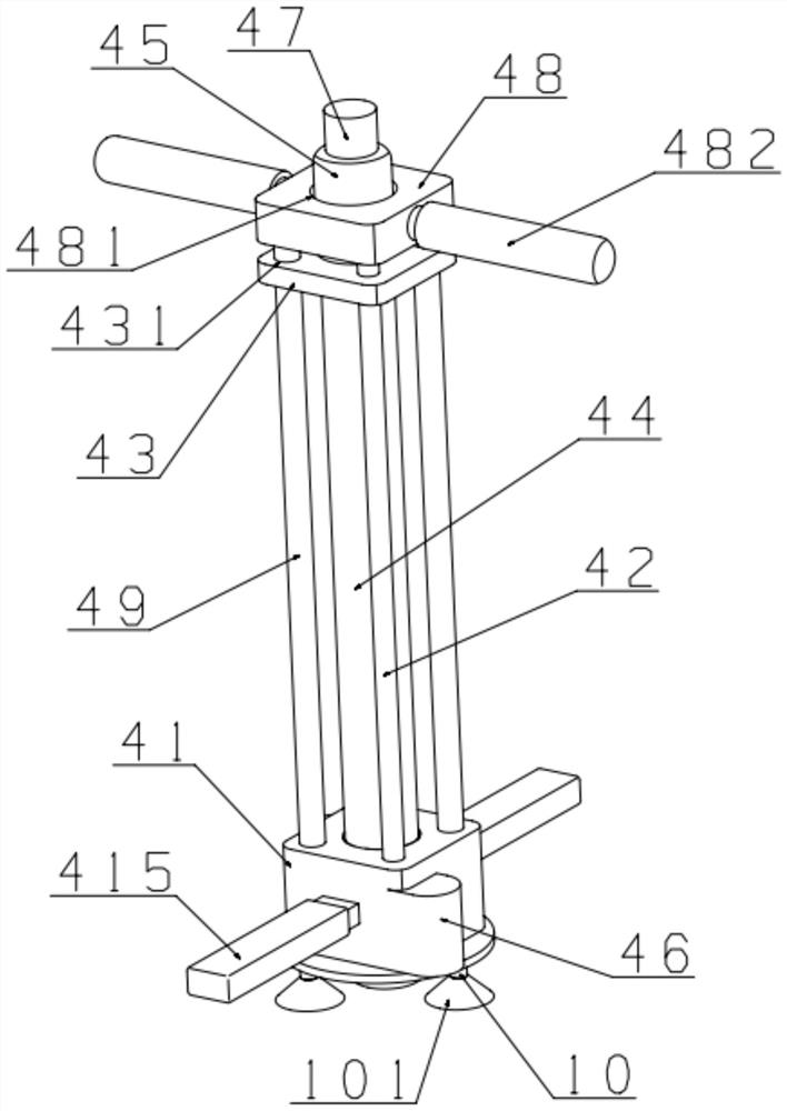
[0051] Such as Figure 1 to Figure 5 As shown, the directional variable flow hydraulic splitting system in this embodiment includes: a main machine box 1, a water tank 11, a booster pump 12, a main controller 2, an operating console 21, a storage battery 3, a shock absorber 31, and a drilling Device 4, frame 41, first end 411, second end 412, first guide hole 413, guide bar 414, first handle 415, guide rail 42, drill seat 43, screw hole 431, drill bit 44, first motor 45 , second motor 46, sub-controller 47, auxiliary seat 48, second guide hole 481, second handle 482, screw 49, expander 5, expansion tube 51, quick connector 52, first water pipe 6, second water pipe 61 , Distribution valve 7, water pressure sensor 8, air conditioner 9, foot 10, foot pad 101.

[0052] The inside of the main box 1 is installed with: a water tank 11, a booster pump 12, a main controller 2, a battery 31 and a distribution valve 7; the main controller 2 is electrically connected to the battery 31 an...

Embodiment 2

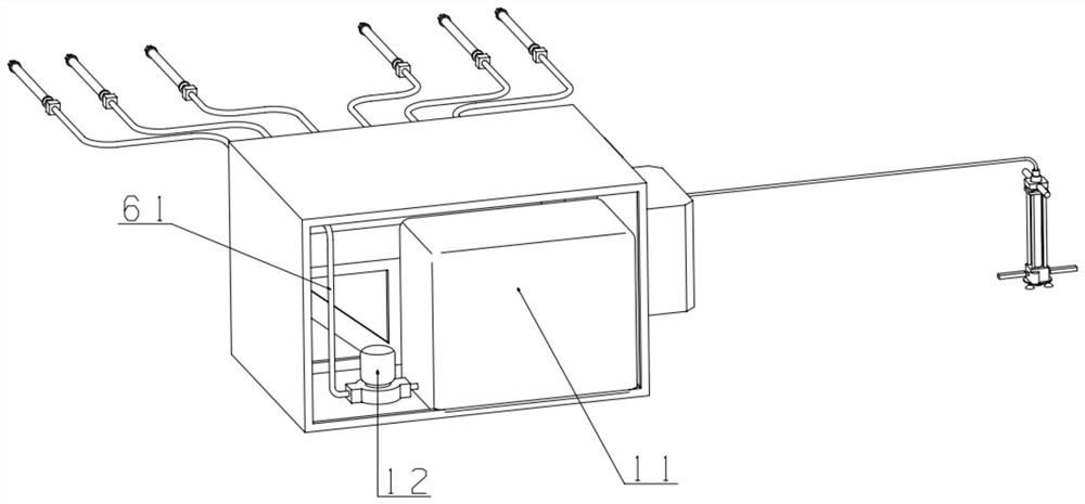
[0056] Such as Figure 6 As shown, the directional variable flow hydraulic splitting method in this embodiment is realized by the directional variable flow hydraulic splitting system in the above embodiment, and specifically includes the following steps:

[0057] S1: Path planning, first plan the rock splitting path and the splitting timing of each splitting point according to the construction conditions on site and the direction of the stone falling, and mark it on the rock wall;

[0058] S2: Drilling and data acquisition, the rock wall is drilled with the marking point on the rock wall of the drilling device 4, and the torque of the first motor 45 and the second motor 46 is collected by the secondary controller 47, and the data is collected. It is transmitted to the main controller 2, and the rock formation hardness at each marked point is obtained through the calculation of the main controller 2, and the cracking critical pressure value at the marked point is calculated at ...


PUM


Abstract

The invention relates to the field of rock breaking equipment, and particularly discloses a directional variable flow type hydraulic fracturing system. The directional variable flow type hydraulic fracturing system comprises a water tank, a pressure pump, a main controller, a storage battery, a distribution valve, a drilling device and expanders. The invention further discloses a directional variable flow type hydraulic fracturing method using the directional variable flow type hydraulic fracturing system. According to the directional variable flow type hydraulic fracturing system and method, the drilling device is used for drilling a rock wall and collecting hardness data of the rock wall at the same time, the main controller is used for calculating to form the fracturing critical pressure intensity at each fracturing point, then the needed fracturing critical pressure intensity of the expanders at each fracturing point is calculated according to the set time sequence, the main controller controls the flow in the expanders by controlling the distribution valve, and therefore the effect of controlling the fracturing time sequence by controlling the pressure intensity is achieved. The system can adjust measures to local conditions, on-site calculation and deployment are achieved, the intelligence is high, judgment can be carried out without human experience, the safety is high, and the error rate is low.

Description

technical field [0001] The invention belongs to the field of rock breaking equipment, in particular to a directional variable flow hydraulic splitting system and method. Background technique [0002] In the process of quarrying or geological research and exploration, it is usually necessary to cut and crush hard rocks. The transmission method is to process rocks through physical cutting, explosive blasting, digging, etc., but not only the efficiency Low, and the risk is very high, often causing serious safety accidents. [0003] In this regard, people have studied a new type of static rock breaking and cutting technology, that is, hydraulic splitting and cutting rock technology; High-pressure water, controlled pressurization, expands the expander radially, compresses the hole wall, and loads hundreds of tons of expansion force to cause directional cracking or random crushing of rock or concrete structures. Compared with traditional rock-breaking methods, it is safer. Funny...

Claims


Application Information

Patent Timeline
Patent Type & Authority Applications(China)
IPC IPC(8): E21C37/12E21B3/02E21B15/00
CPCE21C37/12E21B3/02E21B15/003
Inventor 梁进范怀斌任春刚甘树林巫建军黄国松李基锐苏东华姚方明肖建国袁明农志祥陆少锋陈保健
Owner GUANGXI NEWHARBOR ENG CO LTD
Why Eureka
Try Eureka