Acid pickling and tin injection device for lamp holder connection points

A lamp head connection and tin injection technology, applied in auxiliary devices, welding equipment, electrical components, etc., can solve the problems of easy oxidation of the conical shell, affect the conductivity, and easy dripping of solder, so as to avoid short circuits and enhance conductivity. , the effect of reducing resistance and heating

Pending Publication Date: 2022-01-14
镇江震东电光源有限公司
0 Cites 0 Cited by

AI-Extracted Technical Summary

Problems solved by technology

There are solder contacts on the cap of an incandescent lamp, and the solder contacts are generally formed by injecting tin into a conical shell. However, there are two major problems in the process of injecting tin at present. One is that the conical shell is easy to oxidize, which leads to injecti...

Method used

The present invention is ingenious in design, first removes the oxide layer in the tin injection tank on the lamp cap connection point by pickling, and residual acid can be heated and evaporated, so that solder is connected more closely with the tin injection tank, which enhances electrical condu...

Abstract

The invention discloses an acid pickling and tin injection device for lamp holder connection points, which comprises an acid pickling station and a tin injection station, wherein the acid pickling station and the tin injection station are adjacent and are both arranged on an assembly line, and a lamp holder clamping device is arranged on the assembly line; the acid pickling station comprises an acid injection dropper, the acid injection dropper is arranged over a tin injection groove of a lamp holder connecting point and connected with the first lifting device, the tin injection station comprises a blocking piece, the blocking piece is arranged over the lamp holder connecting point, and a round hole is formed in the position, corresponding to the tin injection groove of the connecting point, of the blocking piece, the blocking piece is connected with the second lifting device through a connecting arm, and a tin injection type electric soldering iron is arranged above the blocking piece. The oxidation layer in the tin injection groove on the connection point of the lamp holder is removed through acid pickling, residual acid can be heated and evaporated, so that soldering tin is connected with the tin injection groove more tightly, conductivity is enhanced, resistance and heat are reduced, the lamp holder is blocked by the blocking piece before tin injection, the soldering tin is injected into the tin injection groove from the round hole of the blocking piece, and short circuit caused by the fact that the soldering tin is splashed to the lamp holder is avoided.

Application Domain

Electrical apparatusSoldering auxillary devices

Technology Topic

MetallurgyLight head +3

Image

  • Acid pickling and tin injection device for lamp holder connection points
  • Acid pickling and tin injection device for lamp holder connection points

Examples

  • Experimental program(1)

Example Embodiment

[0017] In order to deepen the understanding of the present invention, the present invention will be further described below in conjunction with the embodiments and accompanying drawings. The embodiments are only used to explain the present invention and do not constitute a limitation to the protection scope of the present invention.
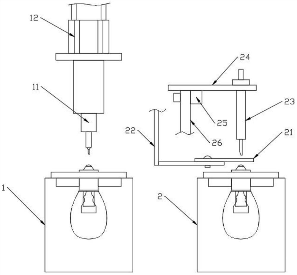
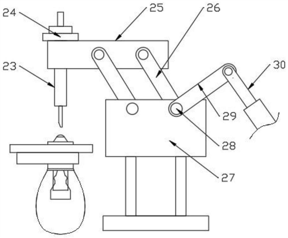
[0018] like Figure 1~2 As shown, a pickling and tin injection device for the connection point of the lamp cap includes a pickling station 1, an acid injection dropper 11, a first lifting device 12, a tin injection station 2, a blocking piece 21, a connecting arm 22, Tin-filling type electric iron 23, connecting plate 24, upper connecting seat 25, rotating arm 26, lower connecting seat 27, rotating shaft 28, connecting rod 29 and telescopic arm 30.
[0019] A pickling and tin injection device for the connection point of the lamp cap, comprising a pickling station 1 and a tin injection station 2, the pickling station 1 and the tin injection station 2 are adjacent to each other and are both arranged on the assembly line, and the assembly line is equipped with With lamp holder device;
[0020] The pickling station 1 includes an acid injection dropper 11. The acid injection dropper 11 is arranged directly above the tin injection tank at the connection point of the lamp head and is connected with the first lifting device 12. The tail of the acid injection dropper 11 is provided with Flexible pipe, the acid dropper 11 is connected with the acid storage container through the flexible pipe;
[0021] The tin injection station 2 includes a stopper 21, which is arranged directly above the connection point of the lamp head. The stopper 21 is provided with a circular hole at the position corresponding to the tin filling tank at the connection point. The stopper 21 passes through the connecting arm 22 Connected with the second lifting device, a tin-injecting electric soldering iron 23 is provided above the blocking plate 21, and the tin-injecting electric soldering iron 23 is connected to the upper connecting seat 25 through a horizontal connecting plate 24, and the upper connecting seat 25 is connected to the lower connecting seat 25 through a rotating arm 26. Connecting seat 27 links to each other, and described rotating arm 26 comprises driven arm and driving arm, and driven arm is all connected by hinge with upper connecting seat 25, lower connecting seat 27, and the upper end of driving arm is hingedly connected with upper connecting seat 25, drives The lower end of the arm is connected with one end of the rotating shaft 28, and the driven arm, the driving arm, the upper connecting seat 25 and the lower connecting seat 27 form a parallelogram structure, and the other end of the rotating shaft 28 passes through the lower connecting seat 27 and links to each other with the connecting rod 29. Rod 29 is in turn connected to telescopic arm 30 .
[0022] Wherein, the assembly line is a turntable, and the driving device of the turntable is a servo motor.
[0023] Wherein, the lamp cap clamping device includes a fixing seat matched with the lamp cap, and a pneumatic gripper is arranged under the fixing seat.
[0024] Wherein, the first lifting device 12 is an air cylinder, and the acid injection dropper 11 is connected with the piston rod of the air cylinder.
[0025] Wherein, the second lifting device is a cylinder, the connecting arm 22 is L-shaped, the horizontal plane of the L-shaped connecting arm 22 is connected with the blocking plate 21, and the vertical surface of the L-shaped cylinder is connected with the piston rod of the cylinder.
[0026] Wherein, a bearing is provided between the rotating shaft 28 and the lower connecting seat 27 .
[0027] The invention is cleverly designed. First, the oxide layer in the tin injection tank on the connection point of the lamp head is removed by pickling, and the residual acid will be heated and evaporated, so that the solder and the tin injection tank are more closely connected, the conductivity is enhanced, and the resistance and To generate heat, block the lamp cap with the baffle 21 before tin injection, so that the solder is injected into the tin injection tank from the round hole of the baffle 21, so as to avoid the short circuit caused by the solder splashing on the lamp cap.
[0028] The above descriptions are only preferred embodiments of the present invention, and are not intended to limit the present invention. Any modifications, equivalent replacements, improvements, etc. made within the spirit and principles of the present invention shall be included in the scope of the present invention. within the scope of protection.

PUM

no PUM

Description & Claims & Application Information

We can also present the details of the Description, Claims and Application information to help users get a comprehensive understanding of the technical details of the patent, such as background art, summary of invention, brief description of drawings, description of embodiments, and other original content. On the other hand, users can also determine the specific scope of protection of the technology through the list of claims; as well as understand the changes in the life cycle of the technology with the presentation of the patent timeline. Login to view more.

Similar technology patents

Recessed lamp

Owner:KUNSHAN BOWEN LIGHTING TECH

Steering engine

InactiveCN108930771Aclosely connectedreduce volume
Owner:北京若唯世纪科技有限公司

Active filter

InactiveCN110752832Aclosely connectedeasy to use
Owner:河南费曼电力技术有限公司

Classification and recommendation of technical efficacy words

  • closely connected
  • Improve conductivity

Precast concrete production line

ActiveCN109834814Aclosely connectedFast shipping
Owner:LANGFANG HESS BUILDING MATERIALS MACHINERY CO LTD +1

Method of improving the electrical conductivity of a conductive ink trace pattern and system therefor

InactiveUS20100231672A1improve electrically conductivityimprove conductivity
Owner:WESTERN MICHIGAN UNIVERSITY
Why Eureka
Try Eureka