Electric welding head of pinpoint welding

A welding head, parallel electrode technology, used in resistance welding equipment, circuits, welding media, etc.

Inactive Publication Date: 2004-02-25
杨仕桐
View PDF0 Cites 1 Cited by
  • Summary
  • Abstract
  • Description
  • Claims
  • Application Information

AI Technical Summary

Problems solved by technology

The insulation separation ga...

Method used


Image

  • Electric welding head of pinpoint welding
  • Electric welding head of pinpoint welding
  • Electric welding head of pinpoint welding

Examples


Embodiment Construction

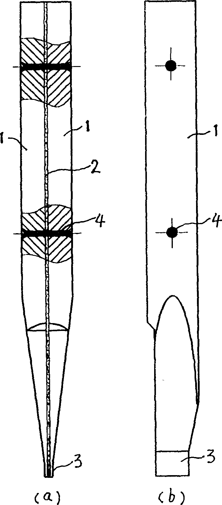
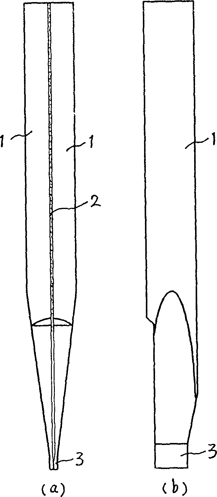
[0013] figure 2 Middle: 1 is the two parallel electrodes of the welding head, which are made of high temperature resistant metal materials (such as tungsten, molybdenum and their alloys, etc.). 2 is an insulating layer, which is bonded by thermosetting insulating adhesive, and the insulation separation gap can be between 0.02-0.15mm. 3 is the tip part of the welding head, the tips of the two electrodes are slightly bent inward, forming ohmic contact with each other, the contact resistance is generally ≤200mΩ, and the rest are separated by insulation layer 2; the tip part 3 of the welding head can also be made Like the existing welding head, the two parallel electrodes are completely insulated and separated by the insulating layer 2 .

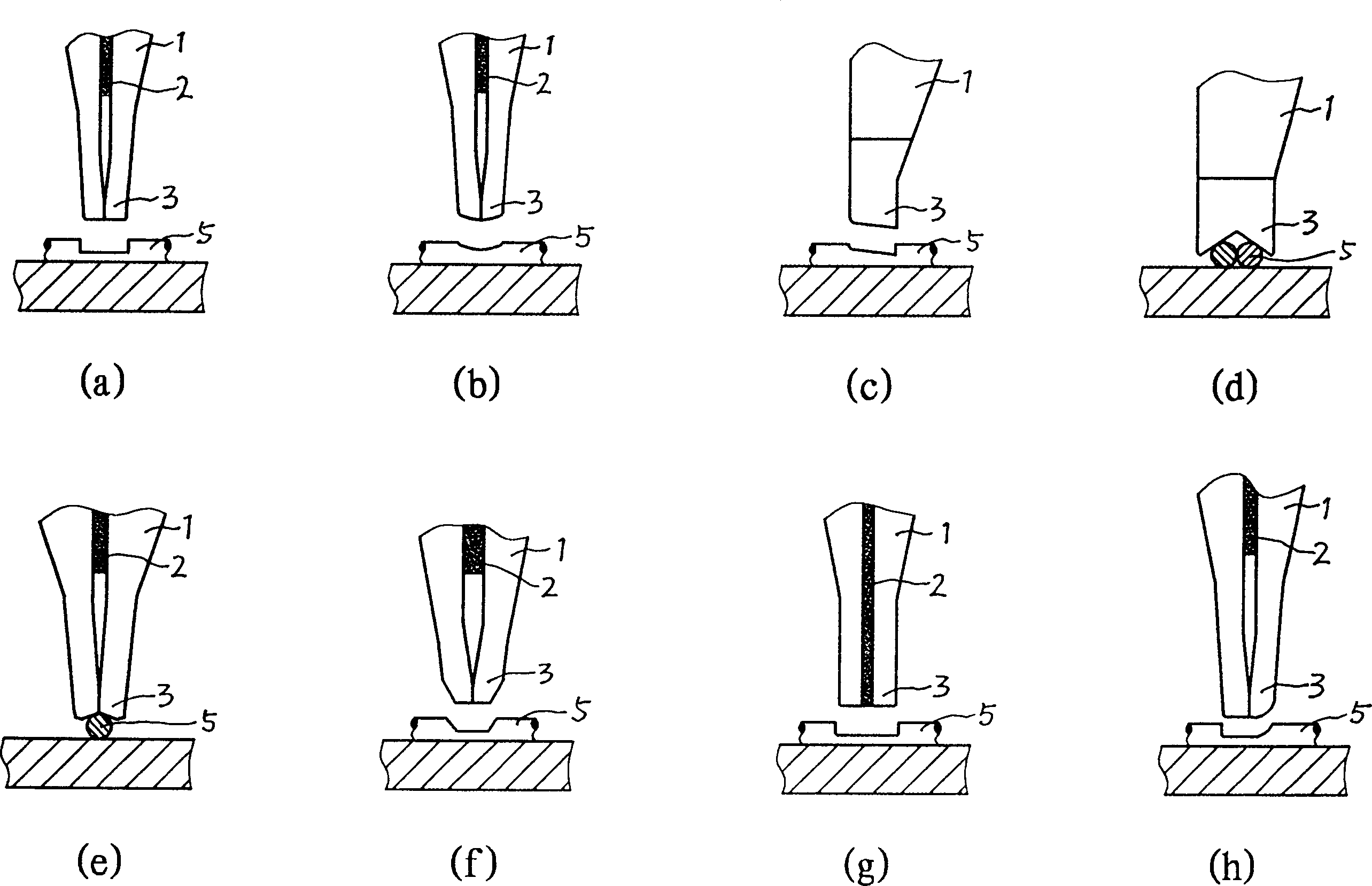
[0014] image 3 Middle: (a) is a welding head with a planar structure at the tip end surface. The tip parts of the two parallel electrodes are made to be in ohmic contact with each other, and the shape of the tip end surface is made into a pl...


PUM


Abstract

The present invention relates to a point electrowelding welding head for the electronic industry and microelectronic industry. It comprises two parallel electrodes which are made of high-temp. resistant metal material, and combined together and an insulating layer sandwiched between two electrodes, and is characterized by that the said insulating layer is made up by adopting insulating viscose capable of producing fix-connecting adhesion and insulating separation actions simultaneously so as to save insulating rivet, and at the same time, the pointed portions of two parallel electrodes are made into the form of mutual ohmic contact so that it not only can directly weld enamelled wire, but also can obtain good welding effect for welding bare wire, metal sheet and metal tape, etc.

Description

technical field [0001] The invention relates to a spot welding head used in the electronics industry and the microelectronics industry. Background technique [0002] Spot welding is a welding process in which a large amount of current passes through two metal bodies to be welded in an instant, and the electric energy is converted into heat energy, which makes the two metal bodies melt. Existing electronic industry, microelectronics industry are used for the spot electric welding head of fine welding such as figure 1 As shown, two parallel electrodes 1 are made of high-temperature-resistant metal. Usually, the two parallel electrodes are machined into two symmetrical φ2-5mm semi-cylindrical bodies with a total length of about 20-40mm, near the tip of the welding head 5- The range of 15mm is then processed into a split shape of about 6°-12°, and processed into a rectangular or square cylinder at the tip. A mica sheet is used as an insulating layer 2 between the two parallel ...

Claims


Application Information

Patent Timeline
IPC IPC(8): B23K11/00B23K11/10B23K11/30
CPCB23K11/105B23K11/0026B23K2201/38B23K11/3009B23K2101/38H01L2224/78282H01L2224/78313
Inventor 杨仕桐
Owner 杨仕桐
Why Eureka
Try Eureka