Inspection method of roller surface laser cladding repair layer

A laser cladding, roll surface technology, applied in material analysis by optical means, analysis of solids using sonic/ultrasonic/infrasonic waves, measurement devices, etc. Defects, good quality effects

Pending Publication Date: 2022-01-21
NANJING IRON & STEEL CO LTD
View PDF10 Cites 0 Cited by
  • Summary
  • Abstract
  • Description
  • Claims
  • Application Information

AI Technical Summary

Problems solved by technology

Therefore, the laser cladding layer on the surface of the roll often has defects such as incomplete fusion, pores, and inclusions. Due to local rapid heating and cooling, residual tensile stress is generated, which in turn leads to crack initiation and expansion, thus affecting the stability and reliability of the formed parts.

Method used


Image

  • Inspection method of roller surface laser cladding repair layer
  • Inspection method of roller surface laser cladding repair layer
  • Inspection method of roller surface laser cladding repair layer

Examples


Embodiment 1

[0030] The surface of the finishing roll of a steel factory was repaired by laser cladding method. The surface hardness of the original roll was 60-70HRC. The total length of the fusion line in the repaired area was about 2000mm, and the area of ​​the repaired area was about 250,000mm. 2 .

[0031] Ultrasonic flaw detection is used to detect flaws in the entire repaired layer area, and there is no defect; flaw detection is carried out within 20mm near the fusion line between the repaired layer and the original roll surface, and there is no defect, which meets the requirements.

[0032] Measure the unevenness of the fusion zone between the repaired layer and the original roll surface. The measurement position is on a straight line perpendicular to the fusion line, with a distance of 50 mm. The repaired layer and the original roll surface area each account for 50%. The extreme difference of surface roughness is 0.5mm, which meets the requirements.

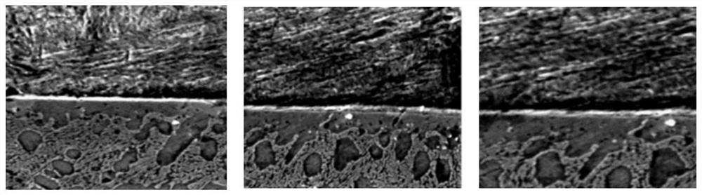
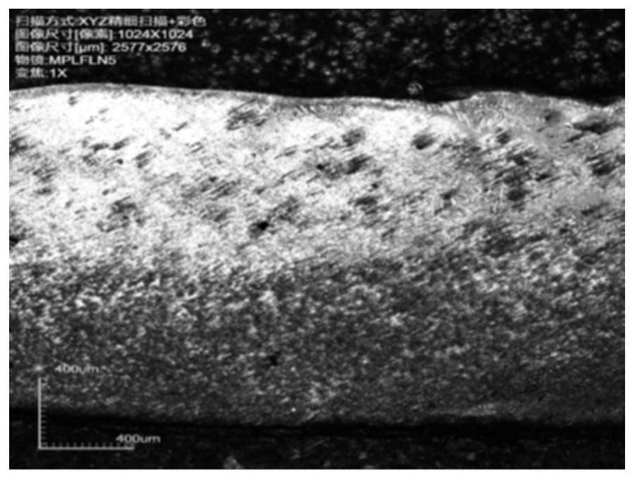
[0033] Metallographic inspec...

Embodiment 2

[0040] The surface of the rough rolling work roll of a steel plant was repaired by laser cladding method. The surface hardness of the original roll was 35-45HRC, the total length of the fusion line in the repair area was 257mm, and the area of ​​the repair area was about 4096mm 2 .

[0041] Ultrasonic flaw detection is used to detect flaws in the entire repaired layer area, and there is no defect; flaw detection is carried out within 20mm near the fusion line between the repaired layer and the original roll surface, and there is no defect, which meets the requirements.

[0042] Measure the unevenness of the fusion zone between the repaired layer and the original roll surface. The measurement position is on a straight line perpendicular to the fusion line, taking a distance of 50mm. The repaired layer accounts for 30% and the original roll surface accounts for 70%. The extreme difference of surface roughness is 1.2mm, which does not meet the requirements.

[0043] As requested, ...

Embodiment 3

[0049] The surface of the finished strip steel roll in a steel plant was repaired by laser cladding. The surface hardness of the original roll was 65-75HRC. The total length of the fusion line in the repaired area was about 800mm, and the area of ​​the repaired area was about 40,000mm. 2 .

[0050] Ultrasonic flaw detection is used to detect flaws in the entire repaired layer area, and there is no defect; flaw detection is carried out within 20mm near the fusion line between the repaired layer and the original roll surface, and there is no defect, which meets the requirements.

[0051] Measure the unevenness of the fusion zone between the repaired layer and the original roll surface. The measurement position is on a straight line perpendicular to the fusion line, with a distance of 50 mm. The repaired layer and the original roll surface area each account for 50%. The extreme difference of surface roughness is 0.7mm, which meets the requirements.

[0052] Metallographic inspec...


PUM

PropertyMeasurementUnit
areaaaaaaaaaaa

Abstract

The invention discloses an inspection method for a laser cladding repair layer on the surface of a roller. The method comprises the following steps of: by using ultrasonic flaw detection, performing flaw detection on a whole repairing layer area, and performing flaw detection on a repairing layer and an original roller surface fusion line; carrying out unevenness measurement on the repair layer and the original roll surface fusion area; carrying out metallographic inspection on the repair layer and the original roll surface fusion area, wherein a metallographic sampling mode is parallel to a fusion line or a tangent line of the fusion line; and carrying out hardness test on the repair layer and the original roll surface fusion region, adopting a Rockwell hardness detection method, sampling in a manner of being vertical to a fusion line, and carrying out multi-point measurement on each sample. The method is used for inspecting the laser cladding repair layer prepared on the surface of the roller, so that the quality of the laser cladding repair layer on the surface of the roller can be effectively judged, and normal operation and use of the repaired roller can be guaranteed.

Description

technical field [0001] The invention belongs to the field of metallurgical engineering, and in particular relates to a method for inspecting a laser cladding repair layer on the surface of a roll. Background technique [0002] The roll is a large part with large volume, heavy mass, and inconvenient processing. After wear and tear, high-performance repair has always been a problem. In the past, surfacing welding was often used for repair or direct replacement, but large parts usually mean transportation inconvenience, high risk, high cost, and labor-intensive time. The surfacing repair takes a long time and is not ideal in terms of economic benefits. Laser cladding is a method of free deposition and forming of metal in a specific area after laser heating and melting. The process is simple and efficient. In recent years, more and more users hope to repair rolls by laser cladding. [0003] Due to the high energy of the laser, the temperature in the cladding area will change dr...

Claims


Application Information

Patent Timeline
Patent Type & Authority Applications(China)
IPC IPC(8): G01N29/04G01N21/84G01B21/30G01N3/44
CPCG01N29/043G01N21/84G01B21/30G01N3/44G01N2291/0289
Inventor 范益李伟李东晖高燕王发仓
Owner NANJING IRON & STEEL CO LTD
Why Eureka
Try Eureka