High-bandwidth differential voltage probe of multistage microstrip transmission line

A microstrip transmission line and differential voltage technology, applied in the direction of measuring current/voltage, measuring electrical variables, instruments, etc., can solve the problems of slow switching edges, switching loss measurement errors, and inability to correctly describe the switching behavior of devices, etc., to improve bandwidth , good comprehensive performance effect

Pending Publication Date: 2022-01-21
CHONGQING UNIV
View PDF0 Cites 0 Cited by
  • Summary
  • Abstract
  • Description
  • Claims
  • Application Information

AI Technical Summary

Problems solved by technology

[0009] Low-bandwidth probes will seriously affect the measurement accuracy of the switching characteristics of wide-bandgap devices, making the switching edges slower, unable to correctly describe the switching behavior of the device, and at the same time bring errors to the measurement of subsequent switching losses
When the switching time of the wide bandgap device is less than 100ns, the loss measurement error caused by the probe bandwidth can exceed 100%
[0010] (2) Cost requirements
[0016] Problem 1: How to characterize the bandwidth limiting factors and improvement paths of differential voltage probes;

Method used


Image

  • High-bandwidth differential voltage probe of multistage microstrip transmission line
  • High-bandwidth differential voltage probe of multistage microstrip transmission line
  • High-bandwidth differential voltage probe of multistage microstrip transmission line

Examples


Embodiment Construction

[0094] Embodiments of the present invention are described below through specific examples, and those skilled in the art can easily understand other advantages and effects of the present invention from the content disclosed in this specification. The present invention can also be implemented or applied through other different specific implementation modes, and various modifications or changes can be made to the details in this specification based on different viewpoints and applications without departing from the spirit of the present invention. It should be noted that the diagrams provided in the following embodiments are only schematically illustrating the basic concept of the present invention, and the following embodiments and the features in the embodiments can be combined with each other in the case of no conflict.

[0095] Wherein, the accompanying drawings are for illustrative purposes only, and represent only schematic diagrams, rather than physical drawings, and should...


PUM


Abstract

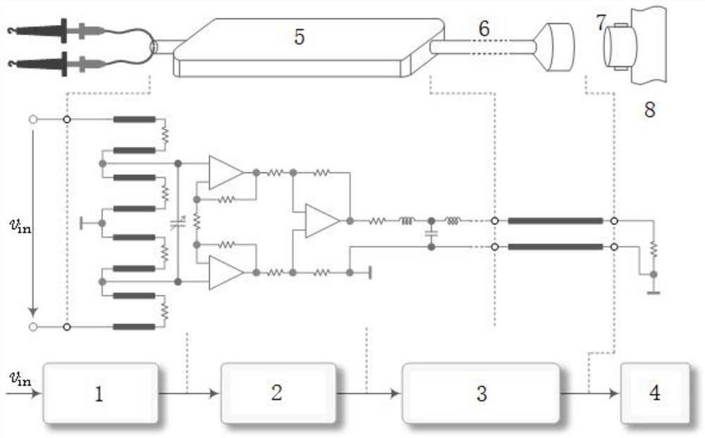
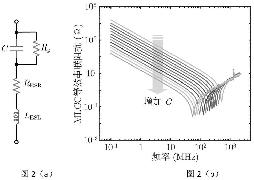
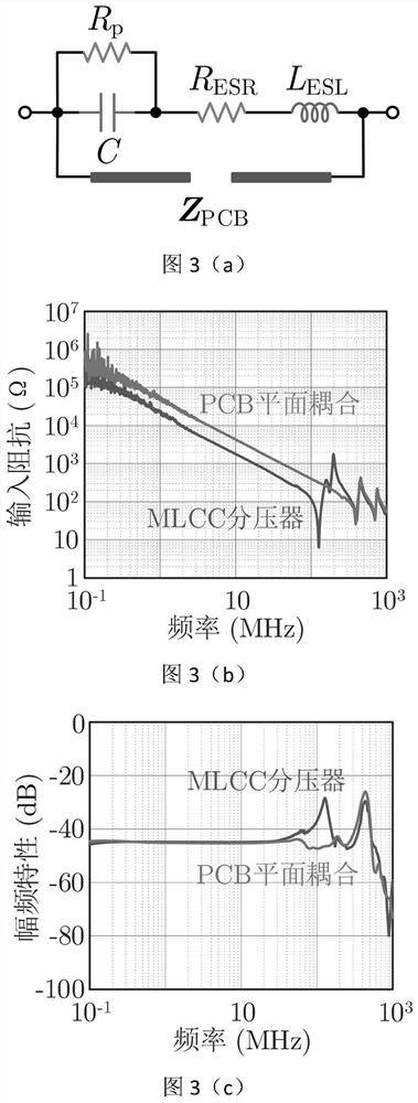
The invention relates to a high-bandwidth differential voltage probe of a multistage microstrip transmission line, and belongs to the field of electronic devices. A voltage division circuit model applicable to a broadband range is established, the influence rule of the size of a voltage divider on the probe bandwidth is analyzed, and a loop compensation method for maximizing the probe bandwidth is provided. Experimental results show that the equivalent series inductance of the multilayer ceramic capacitor and the transmission line effect of PCB plane coupling are bottleneck problems restricting the bandwidth of the differential voltage probe, new structures and new methods such as a high-bandwidth voltage dividing structure based on a parallel plate transmission line, optimization of the length of a voltage bearing arm and high-frequency loop compensation are adopted. The bandwidth limit of the differential probe can be broken through to 500 MHz, and beneficial reference is provided for design, research and development, test characterization and standard formulation of a high-bandwidth differential voltage probe and a wide bandgap device of a multi-stage microstrip transmission line.

Description

technical field [0001] The invention belongs to the field of electronic devices and relates to a high-bandwidth differential voltage probe of a multi-stage microstrip transmission line. Background technique [0002] Compared with Si IGBT, wide bandgap devices represented by silicon carbide (SiC) MOSFET have higher switching speed and lower switching loss, which can effectively improve the power density of electrical equipment. Compared with the switching time of Si IGBT of several microseconds, the switching time of SiC MOSFET is usually tens of nanoseconds, and the switching time of GaN HEMT is even only a few nanoseconds, which puts higher requirements on the performance of the measurement probe. In order to ensure a measurement accuracy of not less than 98%, the bandwidth of the probe is usually required to be more than 5 times the maximum bandwidth of the measured signal, and the bandwidth of the voltage and current probe should not be lower than 400MHz. However, curren...

Claims


Application Information

Patent Timeline
Patent Type & Authority Applications(China)
IPC IPC(8): G01R19/25
CPCG01R19/2503G01R19/2506
Inventor 曾正王宇雷孙鹏王亮
Owner CHONGQING UNIV
Why Eureka
Try Eureka