Backlight assembly

A technology for backlight components and light sources, applied in optical elements, light guides, optics, etc., can solve the problems of uneven heating of aluminum substrates, decreased heat dissipation effect, and impact on the life of light-emitting diode components, and achieve good optical performance, uniform deformation, and good heat dissipation. effect of effect

Pending Publication Date: 2022-01-21
南通创亿达新材料股份有限公司
View PDF4 Cites 0 Cited by
  • Summary
  • Abstract
  • Description
  • Claims
  • Application Information

AI Technical Summary

Problems solved by technology

[0006] On the contrary, although the Chinese utility model patent with the patent number CN202021046294.9 and the patent name of the sub-millimeter light-emitting diode backlight module claims that it can increase the intensity of light by setting grooves on the light incident surface of the light guide plate and embedding light-emitting diodes in the grooves Diffusion stroke to meet the thinning and uniform light effect of the module at the same time; but this patent avoids the heat dissipation problem mentioned in the previous technical solution. The heat dissipation effect is greatly reduced. After the temperature rises, both the customer experience and the life of components including light-emitting diodes will be seriously affected.
[0007] Moreover, since the working temperature of the existing light guide plate is usually controlled below 60-70 degrees Celsius, after placing the lamp beads in the groove based on the prior art, the temperature of the backlight assembly will rise above 70 degrees Celsius, and the existing backlight assembly The conductive lines are all printed on the aluminum substrate compounded with PI film or other insulating layers. When the temperature rises sharply, there are further problems as follows: 1. The uneven heating of the aluminum substrate itself causes warping, resulting in The structure including conductive lines and lamp beads is damaged; 2. The expansion rate of the aluminum substrate and the light guide plate are inconsistent, especially for direct-lit backlight modules applied to large-size displays, the cumulative deformation of large areas is poor It may cause the lamp bead to be resisted by the groove wall when it moves with the substrate, and then cause large-scale damage to the lamp bead
Therefore, due to the limitations of the aforementioned technical problems, the light and thin products that actually place the lamp beads in the groove structure of the light guide plate have not yet appeared.

Method used


Image

  • Backlight assembly
  • Backlight assembly
  • Backlight assembly

Examples


Embodiment 1

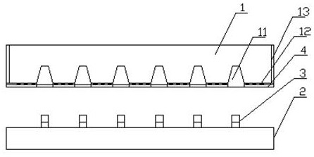
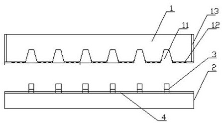
[0028] Such as Figure 1-3 The shown backlight assembly includes a light guide plate 1, a substrate 2, and several light sources 3; the light source can be an LED chip or a lamp bead. The light board includes the board body. The board body can be made of high-temperature resistant PS plastic board or PC plastic board or miniLED packaging glue or high-temperature resistant MS plastic board. You can also choose a glass board with better light transmittance; one side of the board body is the entrance The light surface and the other side are the light-emitting surface, and the light-incoming surface is provided with a number of grooves 11. The molding process of the grooves depends on the material of the light guide plate body; 0.1-1.0mm gap, the distribution method is distributed according to the distribution method of the light source on the substrate; the peripheral side of the board is provided with a first reflective layer, and the rest of the groove on the light incident sur...

Embodiment 2

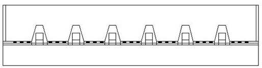
[0029] Embodiment 2: Same as other technical features of Embodiment 1, in order to further enhance the uniformity of light output, a second reflective layer 111 can be provided on the bottom wall of the groove, especially when using LED chips or lamp beads that emit light from the top. This setting is more necessary; combined with Figure 4 As shown, the second reflective layer is not limited to being flat, and may also be curved. The second reflective layer is a reflective sheet or a specular ink layer.

[0030] On the one hand, the function of the heat-conducting reflective layer is to reflect the light emitted by the light source toward the substrate to avoid light leakage; on the other hand, it is to efficiently and uniformly transmit the heat generated by the light source to the substrate to avoid excessive working temperature of the backlight assembly. Existing heat-conducting reflective layers usually use PET-based heat-conducting reflective sheets containing heat-cond...

Embodiment 3

[0031] Embodiment 3: The research and application direction of the mirror ink in the prior art lies in how to improve its reflectivity, and we are surprised to find that on the basis of Embodiment 1, the side of the printed conductive circuit on the substrate, or the entrance of the light guide plate The high-temperature-resistant mirror ink layer formed by glossy screen printing or spraying high-temperature-resistant mirror ink not only has a reflectivity close to 100%, but also can quickly and evenly conduct heat to the substrate, so that the substrate can fully dissipate heat and avoid overheating of the backlight assembly. The high temperature-resistant mirror ink and its preparation method can be, but not limited to, the technical scheme disclosed in the invention patent with the patent application number CN202110687449.X; The choice of points should give consideration to reflective performance and thermal conductivity as much as possible.

[0032]In the above embodiments...


PUM


Abstract

The invention relates to a backlight assembly which comprises a light guide plate, a substrate and a plurality of light sources. A plurality of grooves are formed in the incident surface of the light guide plate, a first reflecting layer is arranged on the peripheral side surface of the plate body, and light guide structures are arranged at the rest parts of the grooves in the incident surface; conductive circuits are sequentially arranged on the substrate; heat-conducting reflecting layers attached to the outer side of the light guide structure are further arranged at the rest parts of the grooves in the light incident surface, or a heat-conducting reflecting layer attached to the outer sides of the conductive circuits is arranged on the substrate; the substrate is attached to the light incident surface of the light guide plate, so that the light sources are arranged in the grooves. The heat conduction and heat dissipation layer is used for fully conducting heat generated by working of the light source to the substrate, the hot spot area is flattened, and the substrate transversely and longitudinally uniformly transfers heat to the outside, so that the backlight assembly has a good heat dissipation effect while achieving lightening and thinning; and the light source, the backlight assembly and other parts connected with the backlight assembly are ensured to be in a proper working temperature environment.

Description

technical field [0001] The invention relates to the technical field of displays, in particular to a backlight assembly. Background technique [0002] The light supply methods of existing LED backlight modules are mainly divided into side-type and direct-type; the side-type structure places the light source on the side of the module, which has the advantage of being able to achieve light and thin structures, but its disadvantages are also obvious: it is difficult to realize Zoned control of light. [0003] The direct-down structure is easy to realize local control of light by setting a plurality of LED lamp beads opposite to the light guide plate to provide light. The light spot makes the existing direct type backlight module thicker. [0004] The patent No. is CN201020003825.6, and the patent name is the Chinese utility model patent of the straight-down light guide plate with grooves at the bottom of the LED backlight module. figure 1 The existing direct-type backlight mo...

Claims


Application Information

Patent Timeline
Patent Type & Authority Applications(China)
IPC IPC(8): G02B6/00
CPCG02B6/0085G02B6/0055G02B6/0016G02B6/0065
Inventor 黄海涛
Owner 南通创亿达新材料股份有限公司
Why Eureka
Try Eureka