Power driver circuit of laser and laser

A driver circuit and laser technology, applied in lasers, laser parts, semiconductor lasers, etc., can solve the problems of increasing the capacity of the cooling system, increasing the rated power of the semiconductor power drive device, and increasing the cost of the laser, so as to reduce power consumption, reduce Low cost and the effect of prolonging the service life

Pending Publication Date: 2022-01-21
天津凯普林光电科技有限公司
View PDF0 Cites 0 Cited by
  • Summary
  • Abstract
  • Description
  • Claims
  • Application Information

AI Technical Summary

Problems solved by technology

As the output power of the laser increases day by day, it is necessary to provide a corresponding amount of current for the laser. However, as the current increases, the power consumption of the laser power drive device increases, and it is necessary to increase the capacity of the cooling system, and also It is necessary to increase the rated power of the semiconductor power drive device, which greatly increases the cost of the laser

Method used


Image

  • Power driver circuit of laser and laser
  • Power driver circuit of laser and laser
  • Power driver circuit of laser and laser

Examples


Embodiment Construction

[0034] In order to make the purpose, technical solution and advantages of the present invention clearer, the technical solution of the present invention will be clearly and completely described below in conjunction with specific embodiments of the present invention and corresponding drawings. Apparently, the described embodiments are only some of the embodiments of the present invention, but not all of them. Based on the embodiments of the present invention, all other embodiments obtained by persons of ordinary skill in the art without making creative efforts belong to the protection scope of the present invention.

[0035] The technical solutions provided by various embodiments of the present invention will be described in detail below in conjunction with the accompanying drawings.

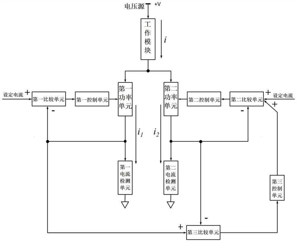
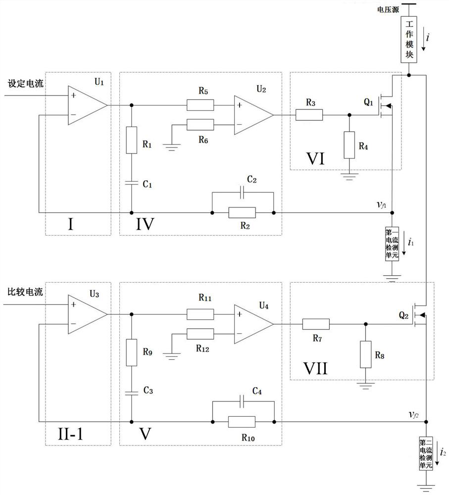
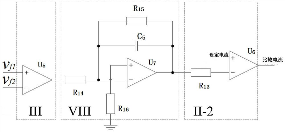
[0036] An embodiment of the present application discloses a laser power driver circuit, such as figure 1 As shown, the power driver circuit includes a control unit and a power unit; the power dr...


PUM


Abstract

The invention discloses a power driver circuit of a laser and the laser. In a power driver circuit, a first power unit and a second power unit are connected in parallel to a working module outside the circuit, and a first current negative feedback control loop is formed by a first current detection unit, a first comparison unit, a first control unit and the first power unit; and the second current detection unit, the third comparison unit, the third control unit, the second comparison unit, the second control unit and the second power unit form a second current negative feedback control loop. Feedback regulation is carried out through the first current negative feedback control loop and the second current negative feedback control loop, and a first path of current flowing through the first power unit and a second path of current flowing through the second power unit are controlled, so that the first path of current and the second path of current are close to set current, and then the total current flowing through the working module is controlled. The power driver circuit has the advantages of low power consumption and long service life.

Description

technical field [0001] The invention belongs to the technical field of laser control, in particular to a laser power driver circuit and the laser. Background technique [0002] In industrial control systems, power drivers are roughly divided into two categories: one is a linear driver, and the other is a pulse width modulated switching driver. Compared with the pulse width modulation switching driver, the linear driver has the advantages of smooth driving, small ripple, no electromagnetic switching noise, no additional smoothing filter inductor, and high bandwidth. Therefore, the power driver of the laser pump source is usually a linear driver. [0003] The stability of the output power of the laser pump source directly determines the stability of the final laser output power of the laser. Since the output power of the laser pump source is proportional to the square of the current flowing through the laser pump source, it is required that the current flowing through the las...

Claims


Application Information

Patent Timeline
Patent Type & Authority Applications(China)
IPC IPC(8): H01S5/042
CPCH01S5/042
Inventor 曹柏林杨宣
Owner 天津凯普林光电科技有限公司
Why Eureka
Try Eureka