Oil-scrap separating and oil cooling centrifugal device

A technology of oil debris separation and centrifugal device, which is applied in centrifuges, centrifuges with rotating drums, etc., can solve the problems of high cost of oil debris separation, inability to efficiently and conveniently separate oil debris, etc., and achieve convenient transportation and recycling Effect

Pending Publication Date: 2022-01-28
南京睿鑫智能制造有限公司
View PDF0 Cites 0 Cited by
  • Summary
  • Abstract
  • Description
  • Claims
  • Application Information

AI Technical Summary

Problems solved by technology

[0004] In view of the above-mentioned technical deficiencies, the purpose of the present invention is to provide an oil debris separation and oil cooling centrifugal device, which drives the centrifuge drum to rotate through the driving equipment, so that the oil in the centrifuge drum is separated from the wear debris, and the wear debris It settles at the bottom of the centrifuge drum and the oil flows out from the open end of the centrifuge drum and is stored in the oil storage chamber; it solves the existing problems of inefficient and convenient oil separation and high cost of oil separation

Method used


Image

  • Oil-scrap separating and oil cooling centrifugal device
  • Oil-scrap separating and oil cooling centrifugal device
  • Oil-scrap separating and oil cooling centrifugal device

Examples


Embodiment 1

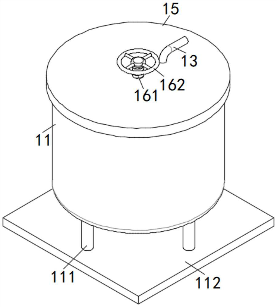
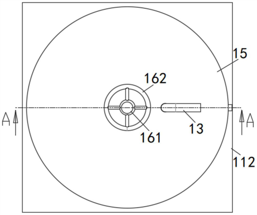
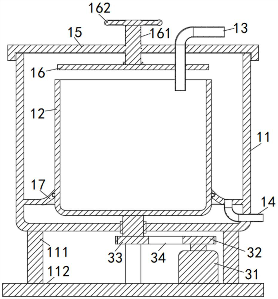
[0030] like Figure 1 to Figure 3 As shown, the present invention provides a kind of oil debris separation and oil cooling centrifugal device, comprising: oil debris separation mechanism and oil cooling mechanism; oil debris separation mechanism includes centrifuge housing 11, centrifuge drum 12, oil inlet pipe 13 and The oil outlet pipe 14; the centrifuge drum 12 is rotated and installed on the inner bottom surface of the centrifuge housing 11; the centrifuge drum 12 is driven to rotate by the driving device; specifically, several support columns 111 are installed at the bottom of the centrifuge housing 11, and the support columns 111 are installed On the support base plate 112; in addition, the driving device includes a servo motor 31, a driving wheel 32, a driven wheel 33 and a drive belt 34; the rotating shaft at the bottom of the centrifuge drum 12 extends out of the bottom surface of the centrifuge housing 11 and is connected to the driven wheel 33 Servomotor 31 is insta...

Embodiment 2

[0036] see Figure 3 to Figure 5 As shown, on the basis of retaining all the technical features in Embodiment 1, the inlet end of the oil cooler pump 23 is connected to the oil pump inlet pipe 231; the outlet end of the oil cooler pump 23 is connected to the oil pump outlet pipe 232; the oil pump inlet pipe 231 extends into Inside the oil cooling box 21 ; the cooled oil is pumped out and recycled through the oil cooler pump 23 to improve the utilization rate of the cooling oil.

[0037] At the same time, an oil level monitoring device is installed on the oil cooling box 21; the oil level monitoring device includes a float 41, a float guide rod 42, a non-contact switch 43 and a signal block 44; A floating ball 41 is installed at one end inside; the floating ball 41 floats on the oil liquid surface in the oil cooling tank 21; Concrete, guide rod support 45 and switch support 46 are installed vertically on oil cooling box 21; Guide rod support 45 upper and lower end sides all in...


PUM


Abstract

The invention discloses an oil-scrap separating and oil-cooling centrifugal device, which belongs to the technical field of oil-scrap separating and cooling, and comprises an oil-scrap separating mechanism and an oil-cooling mechanism, the oil-scrap separating mechanism comprises a centrifugal machine shell, a centrifugal machine rotary drum, an oil inlet pipe and an oil outlet pipe. The centrifuge drum is rotationally mounted on the inner bottom surface of the centrifuge shell; the centrifuge drum is driven by driving equipment to rotate; a sealing cover covers the top end of the centrifugal machine shell; an oil baffle is movably mounted on the inner bottom surface of the sealing cover; the oil cooling mechanism comprises an oil cooling box, an oil cooler and an oil cooler pump. The driving equipment drives the centrifuge drum to rotate, so that oil in the centrifuge drum is separated from abrasive dust, the abrasive dust is precipitated at the bottom in the centrifuge drum, and the oil flows out from the open end of the centrifuge drum and is stored in the oil storage cavity; the oil in the oil storage cavity flows into the oil cooling box from the oil outlet pipe and is cooled by the oil cooler so as to be recycled, and the cost is reduced while the flow speed and the cooling effect of the cooling oil are ensured.

Description

technical field [0001] The invention relates to the technical field of oil debris separation and cooling, in particular to an oil debris separation and oil cooling centrifugal device. Background technique [0002] In the grinding process, with the improvement of the precision of the processed parts and the rapid development of high-speed grinding technology, in addition to choosing reasonable grinding parameters, it is also necessary to improve the circulation quality of the coolant during the grinding process. The purpose of traditional coolant filtration is to remove the grinding debris generated by the coolant during the grinding process. The methods mainly include filter screen or paper tape filter. The filter type filter is mainly to install multiple filter screens on the fuel tank structure to intercept wear debris when the coolant flows back to a specific fuel tank. As time goes by, the filter screen is very easy to clog. As a result, the flow rate of the coolant is...

Claims


Application Information

Patent Timeline
Patent Type & Authority Applications(China)
IPC IPC(8): B04B1/00B04B11/04B04B13/00B04B15/02
CPCB04B1/00B04B11/04B04B13/00B04B15/02
Inventor 毛美琴华明圣侯本松
Owner 南京睿鑫智能制造有限公司
Why Eureka
Try Eureka