Large-tonnage metal bending transmission mechanism

A transmission mechanism, large tonnage technology, applied in the direction of presses, punching machines, manufacturing tools, etc., can solve the problems of large impact, unevenness and low precision of the slider action, and achieve reasonable structural force, simple connection, and reliable rigidity. Effect

Pending Publication Date: 2022-01-28
NANJING UNIV OF POSTS & TELECOMM
View PDF7 Cites 1 Cited by
  • Summary
  • Abstract
  • Description
  • Claims
  • Application Information

AI Technical Summary

Problems solved by technology

[0004] 1. Loud noise, high energy consumption, hydraulic oil leakage and environmental pollution
[0005] 2. The cost is high, because the cost of high-precision parts such as hydraulic cylinders, valve groups, and hydraulic pumps is relatively high. Among them, the middle and high-end markets of valve groups and hydraulic pump components are almost completely dependent on imports, and the cost is high
[0006] 3. The accuracy is not high, and the position accuracy control of the hydraulic system has inherent disadvantages, and the position controllability is poor
[0007] 4. Low service life, wear and tear of components, and pollution of the hydraulic oil circuit are likely to have adverse effects on the stability of the hydraulic system
[0008] 5. The slider action has a large impact and is not smooth
[0009] 6. It is greatly affected by environmental temperature, humidity, dust and other factors
[0010] 7. Complex motion control
[0015] 2. There is no connecting rod mechanism to increase force, so it is only suitable for small tonnage bending machines below 50 tons
[0016] 3. The power utilization rate is low, and the required drive motor power is large, which also increases the cost
[0017] 4. Since the screw rod, the upper beam and the frame are rigidly connected, the drives on both sides cannot be adjusted synchronously
Therefore, the adjustment of parallelism on both sides of the ball screw will cause the screw to bend and damage the screw due to asynchrony.
[0018] 5. Loud noise

Method used


Image

  • Large-tonnage metal bending transmission mechanism
  • Large-tonnage metal bending transmission mechanism
  • Large-tonnage metal bending transmission mechanism

Examples


Embodiment 1

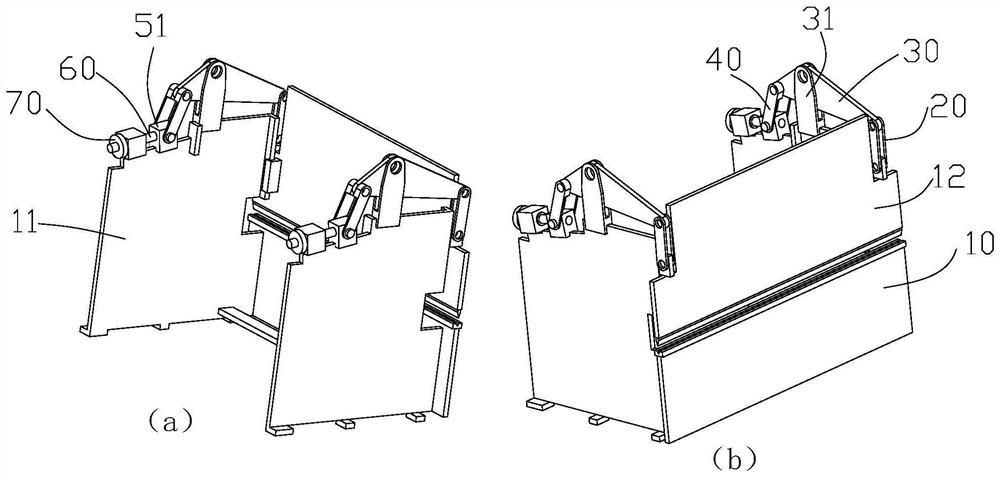
[0073] Such as figure 1 As shown, the sheet metal bending equipment includes a frame 10 and an upper beam 12, wherein the frame includes two symmetrical side plates 11, the upper beam is located directly in front of the two side plates, and can be raised and lowered along the two side plates , the metal bending transmission mechanism in the present invention is used to drive the height of the upper beam.

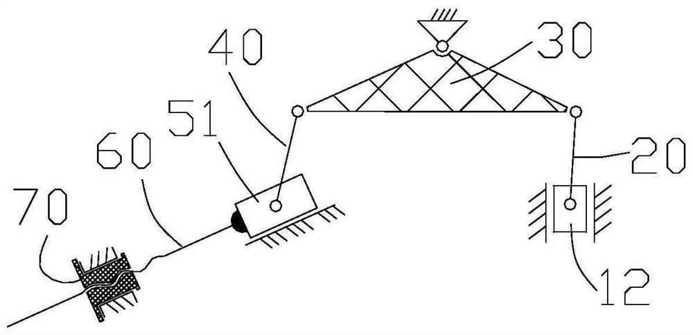
[0074] Such as figure 1 and Figure 5 As shown, a large-tonnage metal bending transmission mechanism includes a connecting rod 20, a pressing arm 30, a hinged support 31, a pressing rod 40, a moving part, a screw rod 60, a nut 70 and a nut rotating drive device.

[0075] There are two pressing arms, which are arranged symmetrically on both sides of the frame of the sheet metal bending equipment, preferably above the tops of the two side plates.

[0076] The above-mentioned pressing arm is equivalent to a lever, with the hinged support as the fulcrum, the combination of th...

Embodiment 2

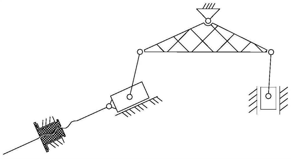
[0097] Such as Figure 5 to Figure 7 As shown, a large-tonnage metal bending transmission mechanism includes a connecting rod 20, a pressing arm 30, a hinged support 31, a pressing rod 40, a moving part, a screw rod 60, a nut 70 and a nut rotating drive device.

[0098] The structures of the pressing arm 20, the connecting rod 30, the hinged support 31, the screw mandrel 60, the nut 70 and the nut rotation driving device are basically the same as those in Embodiment 1, and will not be repeated here.

[0099] The difference is that the structure of the pressing rod and the moving part is different, the moving part is a support rod 52, the bottom end of the pressing rod is hinged with the upper part of the supporting rod, and the lower part of the supporting rod is hinged on the frame; One of the hinges.

[0100] The compression rod and the support rod preferably have the following three embodiments.

[0101] first embodiment

[0102] Such as Figure 6 As shown, the front en...


PUM


Abstract

The invention discloses a large-tonnage metal bending transmission mechanism. The mechanism comprises pressing arms, a connecting rod, a hinge support, a pressing rod, a moving part, a lead screw, a nut and a nut rotation driving device; the two pressing arms are symmetrically arranged on the upper portions of the two sides of a rack of metal plate bending equipment; the front end, facing the upper cross beam, of each pressing arm is hinged to the top end of a connecting rod, and the bottom end of the connecting rod is hinged to the upper cross beam; the middle of each pressing arm is hinged to a hinged support, and the hinged support is fixedly installed on the rack or integrally arranged on the rack; the rear end of each pressing arm is hinged to the top end of a pressing rod, and the bottom end of the pressing rod is hinged to a moving piece; the moving part is mounted at the front end of the screw rod; the nut is arranged on the lead screw in a threaded and sleeving mode and forms lead screw thread pair fit with the lead screw; and the nut is further installed on the machine frame through a bearing seat and can be driven by the nut rotation driving device to rotate. The mechanism can achieve lifting driving of the upper cross beam with the heavy load of 80 tons or above, and the driving noise is low.

Description

technical field [0001] The invention relates to the field of numerical control bending, in particular to a large-tonnage metal bending transmission mechanism. Background technique [0002] At present, CNC plate bending equipment is mainly divided into two types: CNC bending machine and CNC bending center according to the process characteristics, scope of application and degree of automation. Both the CNC bending machine and the CNC bending center include an upper beam, an upper beam lifting drive device and an upper mold arranged at the bottom of the upper beam. [0003] At present, for the lifting drive device of the upper beam of the CNC bending equipment of more than 80 tons, the domestic and foreign markets are mainly driven by hydraulic pressure. Affected by factors such as manufacturing cost, transmission technology, numerical control system, and overall machine structure, the mechanical all-electric servo is still blank. The advantage of the above-mentioned hydrauli...

Claims


Application Information

Patent Timeline
Patent Type & Authority Applications(China)
IPC IPC(8): B21D5/00B30B1/02B30B15/00
CPCB21D5/004B30B1/02B30B15/00
Inventor 徐丰羽杨森范保杰申景金
Owner NANJING UNIV OF POSTS & TELECOMM
Why Eureka
Try Eureka